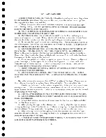
To allow installation of tape by the operator and also to provide freedom of m ove
ment during high-speed rewind, the upper plate is moved upward leaving a gap of
about 27/32 inch between the erase head and the read-w rite head assembly. During
the time when tape is being transported through the machine for reading or writing,
the upper plate is down causing the assem blies to be in close contact with each other.
4 0 4. 1 Read-Write Head Assem bly
The read-w rite head assembly contains the seven read-w rite heads in laminated
form , one behind the other. The tape passes over the head assembly, oxide-side
down. The entire head assembly is removable as a unit; connection to the read-w rite
coils is made through a multi-pin plug at the bottom. The read-write head assembly
should not be removed from the lower plate. It is set at the factory.
4 .4 .2
Erase Head
The erase head is located above and 3 /8 " to the left of the read-write head assem
bly. It consists of one large coil and core covering the entire width of the tape. It
saturates all tracks in one direction during writing just ahead of the portion being
written on. This p rocess erases the information previously written. The head is
kept very close to the read-w rite assembly vertically. A pressure pad is installed to
the right of the erase head to keep intimate contact between the tape and the read -
write head.
As previously stated, the erase head is mounted on the upper plate and moves
up during high-speed rewind time and when the machine is in an unload status.
4 .4 .3
Load Point Sensing
To indicate the beginning of the usable portion of the reel of tape, a small r e
flective spot is placed on the tape (plastic side). This spot is 3 /1 6 " x 1" and is
placed on the front half of the tape width, 1/32" from the edge. It should be located
about ten feet from the physical end of the tape to allow sufficient wind-up on the ma
chine reel.
This reflective spot is sensed by a photo-electric pell arrangement shown in
Figure 9. The light from the front bulb is reflected from the spot to the photo cell
directly to the right of it. This, in turn, operates control circuitry to stop the tape
unit.
4 .4 .4 End-of-Tape Sensing
The end of the usable portion of the reel of tape is indicated by an identical r e
flective spot placed at least 14 feet from the physical end of the tape. This spot is
placed on the plastic side of the tape 1/32" from the back edge. The rear bulb and
photo cell sense this reflective spot in the same manner that the load point is sensed.
4 .4 .5
Tape Brèak
During high-speed rewind, the machine should stop if the tape breaks. An in
dication of tape breakage is provided by directing a light source from the under side
of the tape to the end-of-tape photo cell. Tape normally passes between the light
14
Summary of Contents for 727
Page 6: ......
Page 67: ...co Q...
Page 68: ......
Page 69: ...To Fuse 13 48V...
Page 70: ......
Page 71: ......
Page 72: ......
Page 73: ...o IC To Fuse 13 48V...
Page 74: ......
Page 75: ......
Page 76: ......
Page 78: ......
Page 92: ......
Page 93: ...039 0035 FIGURE 1 BIT PO SITIO N S O N TAPE CURRENT GENERATOR FIGURE 3c...
Page 95: ...w PATH OF TAPE THROUGH MACHINE FIGURE 6...
Page 97: ...SPLIT IDLER ASSEMBLY FIGURE 8...
Page 98: ......
Page 99: ...CLUTCH HOUSING POWDERED IRON AND GRAPHITE MIXTURE FIGURE 10 MAGNETIC CLUTCH...
Page 100: ...PUSH ROD DIAPHRAGM VACUUM COLUMN SWITCHES FIGURE II...
Page 101: ...BACKWARD MOTOR CAPSTAN MOTOR FORWARD MOTOR...
Page 102: ...LATCH FIGURE f3...
Page 103: ...140 140...
Page 107: ...FIGURE 18 HEAD ASSEMBLY A DJUSTM ENTS...
Page 108: ...TAPE C LEA N ER FIG URE 19...
Page 109: ...VACUUM COLUMN ADJUSTMENT FIG U RE 22...
Page 110: ...DRIVE MOTOR PULLEY CAPSTAN DRIVE BELT TENSION FIGURE 23 REAR VIEW S...
Page 113: ...CONTROL UNIT TAPE DRIVE TESTER FIGURE 28 TAPE DRIVE TESTER CO NN EC TIO N S...
Page 116: ...FIGURE 32 HIGH SPEED REWIND...
Page 135: ......
Page 136: ...v n...
Page 137: ......
Page 138: ......
Page 139: ......
Page 140: ......
Page 141: ......
Page 142: ......
Page 143: ......
Page 144: ......
Page 145: ......
Page 146: ......
Page 147: ......
Page 148: ......
Page 149: ......
Page 150: ......
Page 151: ......
Page 152: ......
Page 153: ......
Page 154: ......
Page 155: ......
Page 156: ......
Page 157: ......
Page 158: ......
Page 159: ......
Page 160: ......
Page 161: ......
Page 162: ......
Page 163: ......


