20. 0
PURPOSE OF RELAYS
R l, 18, Run (09.04)
1AU, 1BU (10.01)
1AL (09.06)
1BL (09.04)
18-2 (09.01)
1 8 -3 ,4 (09.03)
R2, Load rewind
(09.04)
2AU (09.04)
2AL (09.04)
2BU (09.06)
2BL (09.05)
They are always picked except when unloaded. When dropped,
they indicate a failure in one of the machine interlocks, such
as a blown fuse, tape breakage, or DC power failure.
When down, they allow full brake to both stop clutches.
It controls phases 1 and 2 AC power.
In case of an interlock failure, drop R4 if it was up, so the
1AU and 1BU pts. can brake both reels.
In case of an interlock failure during low-speed rewind, stop
tape by dropping the manual start line.
Insure that the interlock conditions are satisfied before
allowing the ready line to be raised, or the ready light to be
turned on.
It is picked when the load rewind button is pressed. If this
occu rs in an unload status or in the high-speed area, R2
holds until both capstans are extended. If load rewind button
is pressed when loaded in the slow-speed area, R2 is picked
until the button is released.
P ick R 5, 6, HD7 while rewinding when or if the reel arm switch
is closed, or when the reset key is pressed while rewinding in
the high-speed area.
It is the hold point for R2.
When initiating a rewind in the slow-speed area, it prevents
a short pick to HD8 when R2 drops. (This would occur when
the load rewind button is released, if using manual con trol.)
Pick R3, 31. Trip R21, 26, if latched.
R3, R31, Load rewind
(09.05)
3AU (09.01)
3AL (09.04)
3BU (09.06)
3BL (09.06)
31-2 (09.01)
Same as R2
It shunts the load point and tape end lights during load r e
wind until the capstans extend. This makes the tape break
light brighter during the time it might be used. It also p re
vents the en d -of-file mark from causing a false tape break
indication.
It allows the run relays to hold during load rewind when tape
is not in the columns. It also prevents dropping the run r e
lays if the tape break light burns out during a high-speed
rewind. Dropping the run relays would put full brake on
both reels.
Pick R13 during load rewind until the capstans are out.
(See R13.)
When a rewind in the slow -speed area is initiated, it p re
vents a short pick to HD8 when R2 picks. (This would occur
when the load rewind button is pressed, if using manual
co n tro l.)
Prevent getting a reverse start during load rewind until both
capstans are extended.
85
Summary of Contents for 727
Page 6: ......
Page 67: ...co Q...
Page 68: ......
Page 69: ...To Fuse 13 48V...
Page 70: ......
Page 71: ......
Page 72: ......
Page 73: ...o IC To Fuse 13 48V...
Page 74: ......
Page 75: ......
Page 76: ......
Page 78: ......
Page 92: ......
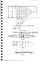
Page 93: ...039 0035 FIGURE 1 BIT PO SITIO N S O N TAPE CURRENT GENERATOR FIGURE 3c...
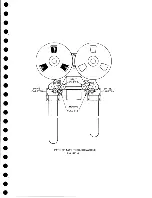
Page 95: ...w PATH OF TAPE THROUGH MACHINE FIGURE 6...
Page 97: ...SPLIT IDLER ASSEMBLY FIGURE 8...
Page 98: ......
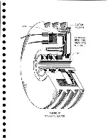
Page 99: ...CLUTCH HOUSING POWDERED IRON AND GRAPHITE MIXTURE FIGURE 10 MAGNETIC CLUTCH...
Page 100: ...PUSH ROD DIAPHRAGM VACUUM COLUMN SWITCHES FIGURE II...
Page 101: ...BACKWARD MOTOR CAPSTAN MOTOR FORWARD MOTOR...
Page 102: ...LATCH FIGURE f3...
Page 103: ...140 140...
Page 107: ...FIGURE 18 HEAD ASSEMBLY A DJUSTM ENTS...
Page 108: ...TAPE C LEA N ER FIG URE 19...
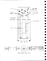
Page 109: ...VACUUM COLUMN ADJUSTMENT FIG U RE 22...
Page 110: ...DRIVE MOTOR PULLEY CAPSTAN DRIVE BELT TENSION FIGURE 23 REAR VIEW S...
Page 113: ...CONTROL UNIT TAPE DRIVE TESTER FIGURE 28 TAPE DRIVE TESTER CO NN EC TIO N S...
Page 116: ...FIGURE 32 HIGH SPEED REWIND...
Page 135: ......
Page 136: ...v n...
Page 137: ......
Page 138: ......
Page 139: ......
Page 140: ......
Page 141: ......
Page 142: ......
Page 143: ......
Page 144: ......
Page 145: ......
Page 146: ......
Page 147: ......
Page 148: ......
Page 149: ......
Page 150: ......
Page 151: ......
Page 152: ......
Page 153: ......
Page 154: ......
Page 155: ......
Page 156: ......
Page 157: ......
Page 158: ......
Page 159: ......
Page 160: ......
Page 161: ......
Page 162: ......
Page 163: ......


