Note:
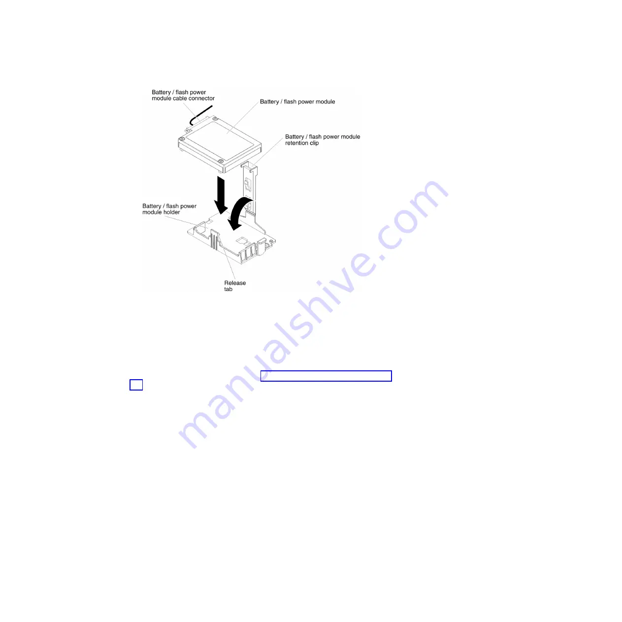
The positioning of the remote battery/flash power module depends
on the type of the remote batteries/flash power module that you install.
b.
Connect the other end of the battery/flash power module cable to the
battery/flash power module cable connector on the battery/flash power
module.
c.
Lower and press down on the retention clip until it snaps in place to hold
the battery/flash power module firmly in place.
7.
Install and lock the left-side cover (see “Installing the left-side cover” on page
205).
What to do next
If you have replaced a component or installed an optional device in the server, you
need to reconnect the power cords and all external cables, and turn on the server
and peripheral devices.
Note:
You must wait approximately 3 minutes after you connect the server power
cord to an electrical outlet before the power-control button becomes active.
250
System x3500 M4 Type 7383: Installation and Service Guide
Summary of Contents for 7383
Page 1: ...System x3500 M4 Type 7383 Installation and Service Guide ...
Page 2: ......
Page 3: ...System x3500 M4 Type 7383 Installation and Service Guide ...
Page 8: ...vi System x3500 M4 Type 7383 Installation and Service Guide ...
Page 42: ...24 System x3500 M4 Type 7383 Installation and Service Guide ...
Page 200: ...182 System x3500 M4 Type 7383 Installation and Service Guide ...
Page 360: ...342 System x3500 M4 Type 7383 Installation and Service Guide ...
Page 416: ...398 System x3500 M4 Type 7383 Installation and Service Guide ...
Page 470: ...452 System x3500 M4 Type 7383 Installation and Service Guide ...
Page 479: ...Taiwan Class A compliance statement Notices 461 ...
Page 480: ...462 System x3500 M4 Type 7383 Installation and Service Guide ...
Page 487: ......
Page 488: ... Part Number 46W8192 Printed in USA 1P P N 46W8192 ...


