7.
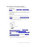
Touch the static-protective package that contains the light path diagnostics
assembly to any unpainted metal surface on the server; then, remove the
assembly from the package.
8.
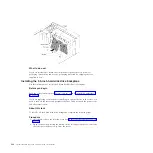
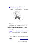
Install the light path diagnostics assembly into the mounting bracket.
9.
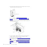
Position the top of the USB cable and light path diagnostics assembly
mounting bracket into the opening and rotate the bottom of the bracket
toward the server until it clicks into place.
10.
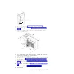
Install the USB cable and light path diagnostics assembly (see “Installing the
USB cable and light path diagnostics assembly” on page 267).
11.
Connect the light path diagnostics cable to the system board.
See“System-board internal connectors” on page 27 and “Internal cable routing
and connectors” on page 186 to locate the USB and light path diagnostics
connectors on the system board.
12.
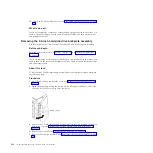
Install the fan cage assembly (see “Installing the fan cage assembly” on page
306).
13.
Install the air baffle (see “Installing the air baffle” on page 211).
14.
Install the bezel (see “Installing the bezel” on page 208).
Chapter 6. Removing and replacing components
271
Summary of Contents for 7383
Page 1: ...System x3500 M4 Type 7383 Installation and Service Guide ...
Page 2: ......
Page 3: ...System x3500 M4 Type 7383 Installation and Service Guide ...
Page 8: ...vi System x3500 M4 Type 7383 Installation and Service Guide ...
Page 42: ...24 System x3500 M4 Type 7383 Installation and Service Guide ...
Page 200: ...182 System x3500 M4 Type 7383 Installation and Service Guide ...
Page 360: ...342 System x3500 M4 Type 7383 Installation and Service Guide ...
Page 416: ...398 System x3500 M4 Type 7383 Installation and Service Guide ...
Page 470: ...452 System x3500 M4 Type 7383 Installation and Service Guide ...
Page 479: ...Taiwan Class A compliance statement Notices 461 ...
Page 480: ...462 System x3500 M4 Type 7383 Installation and Service Guide ...
Page 487: ......
Page 488: ... Part Number 46W8192 Printed in USA 1P P N 46W8192 ...


