13.
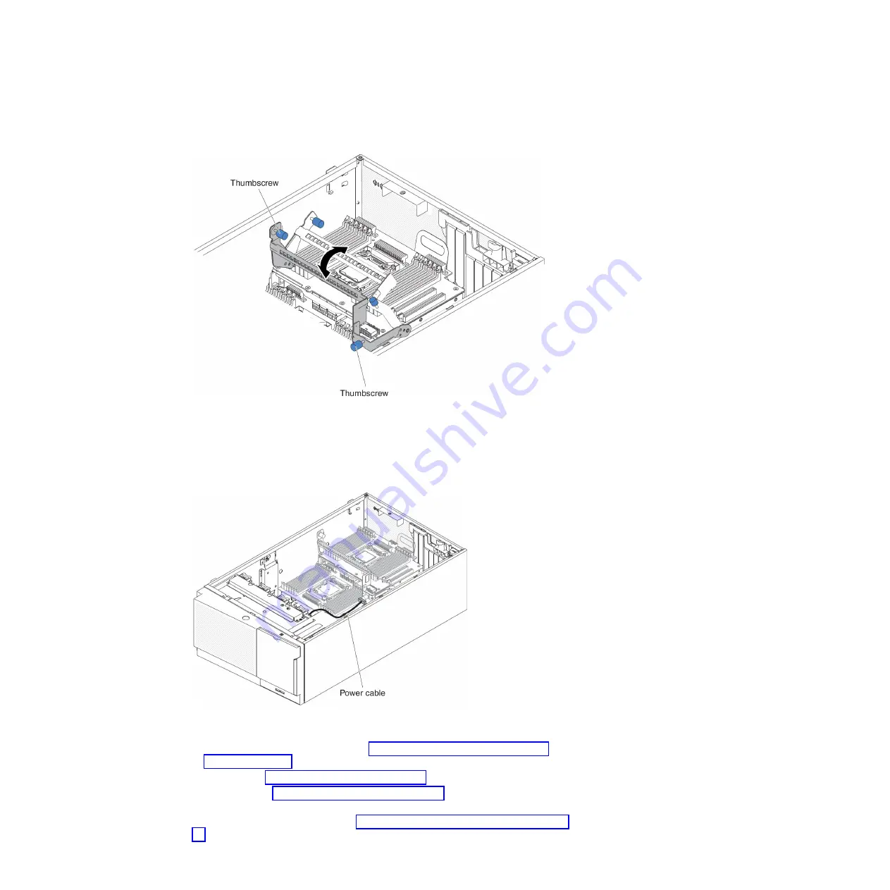
Rotate the release lever toward the front of the server to secure the
microprocessor 2 expansion board in place.
Note:
Press the microprocessor 2 expansion board connector to make sure the
connector is seated securely on the system board.
14.
Fasten the two thumbscrews on the release lever.
15.
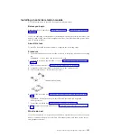
Route the power cable to the microprocessor 2 expansion board power
connector from the power paddle card.
16.
Install any of the following components that you removed from the
microprocessor 2 expansion board:
v
Microprocessor and heat sink (see “Installing a microprocessor and heat
sink” on page 319)
v
DIMMs (see “Installing a DIMM” on page 300)
v
Adapters (see “Installing an adapter” on page 242)
17.
Reconnect any cable to the microprocessor 2 expansion board that you
disconnected during removal (see “System-board internal connectors” on page
27
332
System x3500 M4 Type 7383: Installation and Service Guide
Summary of Contents for 7383
Page 1: ...System x3500 M4 Type 7383 Installation and Service Guide ...
Page 2: ......
Page 3: ...System x3500 M4 Type 7383 Installation and Service Guide ...
Page 8: ...vi System x3500 M4 Type 7383 Installation and Service Guide ...
Page 42: ...24 System x3500 M4 Type 7383 Installation and Service Guide ...
Page 200: ...182 System x3500 M4 Type 7383 Installation and Service Guide ...
Page 360: ...342 System x3500 M4 Type 7383 Installation and Service Guide ...
Page 416: ...398 System x3500 M4 Type 7383 Installation and Service Guide ...
Page 470: ...452 System x3500 M4 Type 7383 Installation and Service Guide ...
Page 479: ...Taiwan Class A compliance statement Notices 461 ...
Page 480: ...462 System x3500 M4 Type 7383 Installation and Service Guide ...
Page 487: ......
Page 488: ... Part Number 46W8192 Printed in USA 1P P N 46W8192 ...


