


Procedure
1.
Carefully turn the server on its side so that it is lying flat, with the cover
facing up.
Attention:
Do not allow the server to fall over.
2.
Unlock and remove the left-side cover (see “Removing the left-side cover” on
page 39).
3.
Remove the fan cage assembly (see “Removing the fan cage assembly” on
page 304).
4.
Touch the static-protective package that contains the microprocessor 2
expansion board to any unpainted metal surface on the server; then, remove
the microprocessor 2 expansion board from the package.
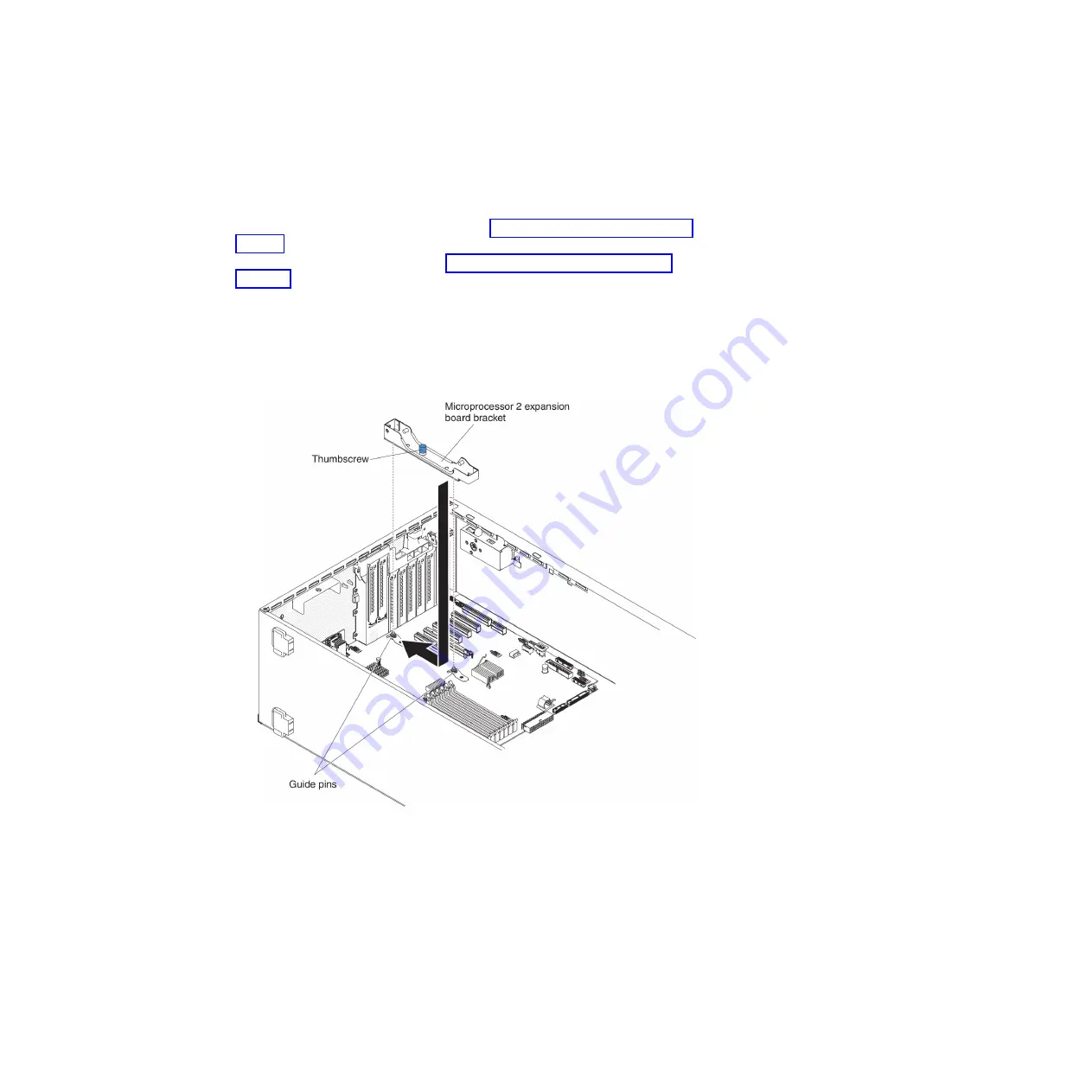
5.
Install the microprocessor 2 expansion board side bracket.
a.
Align the side bracket with the holes on the chassis and install the side
bracket on the system board.
b.
Slide the side bracket toward the rear of the server.
c.
Fasten the thumbscrew on the side bracket.
6.
Install the two guide pins on the system board.
78
System x3500 M4 Type 7383: Installation and Service Guide
Summary of Contents for 7383
Page 1: ...System x3500 M4 Type 7383 Installation and Service Guide ...
Page 2: ......
Page 3: ...System x3500 M4 Type 7383 Installation and Service Guide ...
Page 8: ...vi System x3500 M4 Type 7383 Installation and Service Guide ...
Page 42: ...24 System x3500 M4 Type 7383 Installation and Service Guide ...
Page 200: ...182 System x3500 M4 Type 7383 Installation and Service Guide ...
Page 360: ...342 System x3500 M4 Type 7383 Installation and Service Guide ...
Page 416: ...398 System x3500 M4 Type 7383 Installation and Service Guide ...
Page 470: ...452 System x3500 M4 Type 7383 Installation and Service Guide ...
Page 479: ...Taiwan Class A compliance statement Notices 461 ...
Page 480: ...462 System x3500 M4 Type 7383 Installation and Service Guide ...
Page 487: ......
Page 488: ... Part Number 46W8192 Printed in USA 1P P N 46W8192 ...


