background image

What your server offers

The server uses the following features and technologies:

v

Integrated Management Module

The Integrated Management module (IMM) combines service processor
functions, video controller, and (when an optional virtual media key is installed)
remote presence function in a single chip. The IMM provides advanced
service-processor control, monitoring, and alerting function. If an environmental
condition exceeds a threshold or if a system component fails, the IMM lights
LEDs to help you diagnose the problem, records the error in the event log, and
alerts you to the problem. Optionally, the IMM also provides a virtual presence
capability for remote server management capabilities. The IMM provides remote
server management through the following industry-standard interfaces:

– Intelligent Platform Management Interface (IPMI) version 2.0

– Simple Network Management Protocol (SNMP) version 3

– Common Information Model (CIM)

– Web browser

For additional information, see “Using the integrated management module” on
page 113.

v

UEFI-compliant server firmware

The IBM System x Server Firmware offers several features, including Unified
Extensible Firmware Interface (UEFI) version 2.1 compliance, Active Energy
Management (AEM) technology, enhanced reliability, availability, and
serviceability (RAS) capabilities, and basic input/output system (BIOS)
compatibility support. UEFI replaces the legacy BIOS. UEFI defines a standard
interface between the operating system, platform firmware and external devices,
and offers capabilities that far exceeds that of the legacy BIOS.

The server design combines the UEFI capabilities and features with legacy BIOS
compatibility. The server is capable of booting UEFI-compliant operating systems,
BIOS-based operating systems, and BIOS-based adapters as well as
UEFI-compliant adapters.

Note:

The server does not support DOS (Disk Operating System).

v

IBM Dynamic System Analysis Preboot diagnostics programs

The Dynamic System Analysis (DSA) Preboot diagnostics programs are stored
on the integrated USB memory. It collects and analyzes system information to aid
in diagnosing server problems. The diagnostic programs collect the following
information about the server:

– System configuration

– Network interfaces and settings

– Installed hardware

– Light path diagnostics status

– Service processor status and configuration

– Vital product data, firmware, and UEFI (formerly BIOS) configuration

– Hard disk drive health

– RAID controller configuration

– Event logs for ServeRAID controllers and service processors

The DSA program creates a chronologically ordered merge of the system-event
log (as the IPMI event log), the IMM event log (as the ASM event log), and the
operating system logs. The information is collected into a file that you can send

Chapter 1. The System x3400 M2 server

9

Summary of Contents for 783722U

Page 1: ...System x3400 M2 Types 7836 and 7837 Installation and User s Guide...

Page 2: ......

Page 3: ...System x3400 M2 Types 7836 and 7837 Installation and User s Guide...

Page 4: ...IBM Safety Information IBM Environmental Notices and User s Guide and the Warranty and Support Information document on the IBM System x Documentation CD Fourth Edition April 2011 Copyright IBM Corpor...

Page 5: ...31 Optional two slot PCI extender card 32 Installation guidelines 32 System reliability guidelines 33 Working inside the server with the power on 34 Handling static sensitive devices 34 Removing the l...

Page 6: ...b interface 116 Enabling the Broadcom Gigabit Ethernet Utility program 116 Configuring the Broadcom Gigabit Ethernet controller 117 Using LSI Configuration Utility program 117 Starting the LSI Configu...

Page 7: ...public of China Class A warning statement 127 Taiwan Class A compliance statement 127 Japan Electronics and Information Technology Industries Association JEITA statement 128 Japanese Voluntary Control...

Page 8: ...vi System x3400 M2 Types 7836 and 7837 Installation and User s Guide...

Page 9: ...tuotteen lue turvaohjeet kohdasta Safety Information Avant d installer ce produit lisez les consignes de s curit Vor der Installation dieses Produkts die Sicherheitshinweise lesen Prima di installare...

Page 10: ...For example if a caution statement begins with a number 1 translations for that caution statement appear in the IBM Safety Information book under statement 1 Be sure to read all caution and danger st...

Page 11: ...quipment when there is evidence of fire water or structural damage v Disconnect the attached power cords telecommunications systems networks and modems before you open the device covers unless instruc...

Page 12: ...battery replace it only with the same module type made by the same manufacturer The battery contains lithium and can explode if not properly used handled or disposed of Do not v Throw or immerse into...

Page 13: ...he device v Use of controls or adjustments or performance of procedures other than those specified herein might result in hazardous radiation exposure DANGER Some laser products contain an embedded Cl...

Page 14: ...vice and the power switch on the power supply do not turn off the electrical current supplied to the device The device also might have more than one power cord To remove all electrical current from th...

Page 15: ...esent inside any component that has this label attached There are no serviceable parts inside these components If you suspect a problem with one of these parts contact a service technician Statement 1...

Page 16: ...not exceed branch circuit protection requirements Refer to the information that is provided with your device for electrical specifications Statement 15 CAUTION Make sure that the rack is secured prop...

Page 17: ...N Do not place any object on top of rack mounted devices This server is suitable for use on an IT power distribution system whose maximum phase to phase voltage is 240 V under any distribution fault c...

Page 18: ...xvi System x3400 M2 Types 7836 and 7837 Installation and User s Guide...

Page 19: ...er contains IBM Enterprise X Architecture technologies which help increase performance reliability and availability For more information see What your server offers on page 9 and Reliability availabil...

Page 20: ...an illustration of the 3 5 inch hot swap SAS or SATA server model The following is an illustration of the 2 5 inch hot swap SAS or SATA server model 2 System x3400 M2 Types 7836 and 7837 Installation...

Page 21: ...Procedures for locating firmware and documentation might vary slightly from what is described in this document 1 Go to http www ibm com systems support 2 Under Product support click System x 3 Under...

Page 22: ...anufacturer are on a tag that is attached to the keys If you plan to install the server in a rack you must purchase a Tower to Rack conversion kit The IBM System x Documentation CD The IBM System x Do...

Page 23: ...der it Click the plus sign to display the additional documents When you select a document a description of the document is displayed under Topic Description To select more than one document press and...

Page 24: ...ing steps Note Changes are made periodically to the IBM Web site The actual procedure might vary slightly from what is described in this document 1 Go to http www ibm com systems support 2 Under Produ...

Page 25: ...AID BR10i SAS SATA adapter that provides RAID levels 0 1 and 1E comes standard on some hot swap SAS and hot swap SATA models v An optional ServeRAID MR10i SAS SATA adapter that provides RAID levels 0...

Page 26: ...the two slot extender card Video controller v Matrox G200eV video on system board v Compatible with SVGA and VGA Diagnostic LEDs v Fan v Microprocessor v Memory v Power supply v Voltage regulator mod...

Page 27: ...bilities and basic input output system BIOS compatibility support UEFI replaces the legacy BIOS UEFI defines a standard interface between the operating system platform firmware and external devices an...

Page 28: ...rGuide Setup and Installation CD on page 111 v Active Energy Manager The IBM Active Energy Manager solution is an IBM Systems Director plug in that measures and reports server power consumption as it...

Page 29: ...n about the adapters that are supported and creating RAID arrays v Symmetric multiprocessing SMP The server supports up to two Intel Xeon microprocessors Each microprocessor provides symmetric multipr...

Page 30: ...up system configuration and redundant array of independent disks RAID configuration v Built in monitoring for fan power temperature and voltage v Cooling fans with speed sensing capability v Customer...

Page 31: ...System health v Monitoring v Updates v Event notification v Automation for managed systems The IBM Systems Director Web and command line interfaces provide a consistent interface that is focused on d...

Page 32: ...te wss docdisplay lndocid SERV XPRESS brandind 5000008 or complete the following steps Note Changes are made periodically to the IBM Web site The actual procedure might vary slightly from what is desc...

Page 33: ...The following illustration shows the 3 5 inch SAS SATA hot swap hard disk drive model Chapter 1 The System x3400 M2 server 15...

Page 34: ...The following illustration shows the 2 5 inch SAS SATA hot swap hard disk drive model 16 System x3400 M2 Types 7836 and 7837 Installation and User s Guide...

Page 35: ...e server is connected to ac power the power control becomes active Flashing slowly once per second The server is turned off and is ready to be turned on You can press the power control button to turn...

Page 36: ...lso is visible on the SAS SATA backplane next to the drive connector The backplane is the printed circuit board behind drive bays 4 through 7 on 3 5 inch hard disk drive models and bays 4 through 19 o...

Page 37: ...OM 1 USB 4 USB 3 USB 2 USB 1 System management Ethernet connector Ethernet 1 10 100 1000 Ethernet 2 10 100 1000 NMI button Ethernet transmit receive activity LED Ethernet link status LED Ethernet tran...

Page 38: ...the IBM System x Documentation CD Power error Fault LED When this amber LED is lit it indicates that the power supply has failed For any other combination of LEDs see the Problem Determination and Se...

Page 39: ...processor the Integrated Management Module is shut down however the server can respond to requests to the service processor such as a remote request to turn on the server The power on LED flashes to i...

Page 40: ...an one power cord To remove all electrical current from the device ensure that all power cords are disconnected from the power source 1 2 The server can be turned off in any of the following ways v Yo...

Page 41: ...If the server is not working correctly see the Problem Determination and Service Guide for diagnostic information This chapter provides detailed instructions for installing optional hardware devices i...

Page 42: ...System board internal connectors The following illustration shows the internal connectors on the system board 24 System x3400 M2 Types 7836 and 7837 Installation and User s Guide...

Page 43: ...per number Jumper name Jumper setting JP1 Clear CMOS jumper v Pins 1 and 2 Normal default This keeps the CMOS data v Pins 2 and 3 This clears the CMOS data which clears the power on password and admin...

Page 44: ...in on the SW6 switch block Table 3 System board switches Switch pin number Default value Description 1 Off Reserved 2 Off Power on password override Changing the position of this switch bypasses the p...

Page 45: ...default off 2 Reserved default off 3 Reserved default off 4 When this switch is off TPM physical present is de asserted default off When this switch is on TPM physical present is asserted Important 1...

Page 46: ...on TPM physical present is asserted Notes 1 Before you change any switch settings or move any jumpers turn off the server then disconnect all power cords and external cables Review the information in...

Page 47: ...System board external connectors The following illustration shows the external input output I O connectors on the system board Chapter 2 Installing optional devices 29...

Page 48: ...System board option connectors The following illustration shows the system board connectors for user installable optional devices 30 System x3400 M2 Types 7836 and 7837 Installation and User s Guide...

Page 49: ...about the system board LEDs see the Problem Determination and Service Guide on the IBM System x Documentation CD Optional one slot PCI extender card The following is an illustration of the one slot P...

Page 50: ...n at maximum levels of performance To download firmware updates for your server complete the following steps 1 Go to http www ibm com systems support 2 Under Product support click System x 3 Under Pop...

Page 51: ...server and operating system support hot swap capability you can remove or install the component while the server is running Orange can also indicate touch points on hot swap components See the instru...

Page 52: ...into the server as you lean over it v Avoid dropping any metallic objects such as paper clips hairpins and screws into the server Handling static sensitive devices Attention Static electricity can dam...

Page 53: ...v Take additional care when handling devices during cold weather Heating reduces indoor humidity and increases static electricity Chapter 2 Installing optional devices 35...

Page 54: ...connect all power cords and external cables 3 Unlock the left side cover 4 Press the cover release latch down as shown in the illustration then remove the cover and set it aside Left side cover Cover...

Page 55: ...from the server 4 If you want to remove the bezel completely press the retention tabs on the hinge assembly toward each other and pull the hinge assembly out of the chassis Note While pressing the re...

Page 56: ...left side cover Note You must unlock the left side cover to open or remove the bezel When you lock the server left side cover it locks both the cover and the bezel 3 Grasp the pull point area on the l...

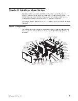
Page 57: ...Chapter 2 Installing optional devices 39...

Page 58: ...nal cables 3 Remove the hot swap power supply or power supplies if any are installed see Installing a redundant power supply on page 82 4 Unlock and remove the left side cover see Removing the left si...

Page 59: ...its closed position complete the following steps 1 Rotate the power supply cage back slightly then push down on the release tab on the rear power supply support bracket Power supply support bracket P...

Page 60: ...ant power supply on page 82 6 Reconnect the external cables and power cords then turn on the attached devices and turn on the server Removing the air baffle To remove the air baffle complete the follo...

Page 61: ...t is over the DIMMs in the rear of the server Air baffle Air baffle pinch tab Removing the fan cage assembly To remove the fan cage assembly complete the following steps 1 Read the safety information...

Page 62: ...ft up the power supply cage handle and pull the power supply cage assembly all the way up until the retainer latch locks the cage in place on the chassis 7 Remove the air baffle see Removing the air b...

Page 63: ...sembly release buttons on both sides of the chassis to release the fan cage assembly from the connector on the chassis Lift the fan cage assembly up and out of the chassis and set it aside Chapter 2 I...

Page 64: ...rank 2 dual rank 4 quad rank ff is the device organization bit width 4 x4 organization 4 DQ lines per SDRAM 8 x8 organization 16 x16 organization wwwww is the DIMM bandwidth in MBps 6400 6 40 GBps PC...

Page 65: ...lots 3 and 6 v When you install additional DIMMs in independent mode install them in the order shown in the following table to optimize system performance All three channels on the memory interface fo...

Page 66: ...all DIMMs in these connectors v When you install or remove DIMMs the server configuration information changes When you restart the server the system displays a message that indicates that the memory c...

Page 67: ...DIMM 9 reserved DIMM 8 DIMM 7 DIMM 6 DIMM 5 DIMM 4 reserved DIMM 3 DIMM 2 DIMM 1 reserved Do not insert a memory DIMM in this connector This DIMM slot is not supported in this model Do not insert a m...

Page 68: ...t down into the connector by applying pressure on both ends of the DIMM simultaneously The retaining clips snap into the locked position when the DIMM is firmly seated in the connector If there is a g...

Page 69: ...If you have other options to install or remove do so now otherwise go to Completing the installation on page 97 Chapter 2 Installing optional devices 51...

Page 70: ...d the locations of the drive bays Your hardware might differ depending on the model The following illustration shows the locations of the drive bays in the 2 5 inch hot swap SAS or hot swap SATA hard...

Page 71: ...server models The following illustration shows the locations of the drive bays in the 3 5 inch simple swap SATA hard disk drive server models The following notes describe the types of drives that the...

Page 72: ...tall removable media drives only in bays 1 2 and 3 v To install a 3 5 in drive in a 5 25 in bay you must use a 5 25 in conversion kit v The electromagnetic interference EMI integrity and cooling of th...

Page 73: ...rnal cables 3 Unlock the left side cover 4 Remove the left side cover see Removing the left side cover on page 36 5 Open the bezel Place your finger on the pull point area on the left side of the beze...

Page 74: ...tion exposure DANGER Some laser products contain an embedded Class 3A or Class 3B laser diode Note the following Laser radiation when open Do not stare into the beam do not view directly with optical...

Page 75: ...Lift the fan cage assembly up and out of the chassis and set it aside 10 Touch the static protective package that contains the DVD drive to any unpainted metal surface on the server then remove the DV...

Page 76: ...a 5 25 in drive in bay 2 push the drive into the bay until it locks into place If you are installing a 3 5 in drive in bay 2 attach the 5 25 in conversion kit and push the drive into the drive bay 14...

Page 77: ...supply cage assembly into the chassis 19 Close the bezel If you have other options to install or remove do so now otherwise go to Completing the installation on page 97 Installing an optional tape dr...

Page 78: ...see Removing the air baffle on page 42 8 Remove the fan cage assembly Press in on the fan cage assembly release buttons on the sides of the chassis to release the fan cage assembly from the connector...

Page 79: ...with the supplied screws 14 Connect one of the connectors on the optical drive power cable to the tape drive If however you are installing an RDX internal USB tape drive you will need to install the S...

Page 80: ...the plastic slots on the bottom of the chassis underneath the fan cage assembly as shown in the following illustration Optical drive power cable SATA optical drive signal cable USB signal cable USB s...

Page 81: ...hard disk drives in the four bay models is to install the drives starting from the left bay bay 4 and go to the right bay bay 7 in that order v The sequence for installing the 2 5 inch hard disk driv...

Page 82: ...bezel off the server and set it aside if you want to remove it completely 5 Remove the EMC shield from the bay in which you want to install the drive 6 Touch the static protective package that contai...

Page 83: ...is operating correctly You might have to restart the server before the drive is recognized If the amber hard disk drive status LED for a drive is lit continuously it indicates that the drive is faulty...

Page 84: ...and backplane that are connected to hot swap models Table 10 IDs for the four bay 3 5 inch hot swap drive models Drive bay number ID Drive bay 4 0 Drive bay 5 1 Drive bay 6 2 Drive bay 7 3 Table 11 ID...

Page 85: ...cover 4 Remove the left side cover see Removing the left side cover on page 36 5 Open the bezel Place your finger on the pull point area on the left side of the bezel door and rotate it away from the...

Page 86: ...eated 11 See Power and signal cables for internal drives on page 69 and the Problem Determination and Service Guide for cabling information if needed 12 Close the drive bay EMC shield 13 Close the bez...

Page 87: ...or on the split end of the cable to the Simple swap SATA signal cable connector on the system board The other end of the combination signal power cable has a signal cable connected to each drive bay s...

Page 88: ...ng on your server model v Locate the documentation that comes with the adapter and follow those instructions in addition to the instructions in this section If you must change the switch setting or ju...

Page 89: ...roperly on UEFI based servers make sure that the adapter firmware level is updated to at least 11 x x XXX and the supporting drivers Attention Some cluster solutions require specific code levels or co...

Page 90: ...ective package Avoid touching the components and gold edge connectors on the adapter 9 If you are installing a full length adapter remove the blue adapter guide if any from the end of the adapter Adap...

Page 91: ...nly by a trained service technician v Read the documentation that comes with the microprocessor to determine whether you have to update the server firmware To download the most current level of the fi...

Page 92: ...ng levels within the same server model is supported You do not have to install the microprocessor with the lowest stepping level and features in microprocessor socket 1 v The microprocessor speeds are...

Page 93: ...e system board b Turn the VRM so that the VRM keys align correctly with the slot connector c Firmly press the VRM straight down into the connector by applying pressure on both ends of the VRM simultan...

Page 94: ...nd number 1 in the socket before you try to close the latch d Align the microprocessor with the socket note the alignment mark and the position of the notches then carefully place the microprocessor o...

Page 95: ...heat sink see the Problem Determination and Service Guide for information on applying thermal grease d Align the heat sink above the microprocessor with the thermal grease side down e Tilt the heat s...

Page 96: ...er supply cage assembly back into the server Press the power supply cage release tab and rotate the power supply cage assembly into the chassis If you have other options to install or remove do so now...

Page 97: ...ts nearby To remove a power supply complete the following steps 1 Read the safety information that begins on page vii and Installation guidelines on page 32 2 Turn off the server and all attached devi...

Page 98: ...omponents in the server 6 While you support the power supply remove the three screws from the pivot bracket that secure the power supply to the chassis then lift the power supply off the chassis Save...

Page 99: ...th the corresponding screw holes on the rear of the chassis 2 While you support the power supply cage install the three screws that secure the power supply to the chassis 3 Connect the cables from the...

Page 100: ...information that begins on page vii and Installation guidelines on page 32 2 Remove the left side cover see Removing the left side cover on page 36 for more information Attention To ensure proper syst...

Page 101: ...er for more than 2 minutes with the left side cover removed To remove a hot swap fan complete the following steps 1 Read the safety information that begins on page vii and Installation guidelines on p...

Page 102: ...low do not operate the server for more than 2 minutes with the left side cover removed To install a hot swap fan complete the following steps 1 Touch the static protective package that contains the ho...

Page 103: ...onnecting power and signal cables to internal drives v The drives that are preinstalled in the server come with power and signal cables attached If you replace any drives remember which cable is attac...

Page 104: ...ow the cabling information for installing the SATA to traditional power converter cable when you install an RDX internal USB tape drive in the server This cable comes with the server in the plastic ba...

Page 105: ...ation shows the cable connectors on the ServeRAID BR10i controller ServeRAID BR10i controller Cable connector for drives 4 7 Cable connector for drives 0 3 1 0 The following illustration shows the cab...

Page 106: ...four 3 5 inch hot swap hard disk drives v The following illustration shows the internal power and configuration cable routing v The following illustration shows the internal signal cable routing for i...

Page 107: ...signal cable routing for installing a ServeRAID MR10i SAS SATA adapter 2 For server models with eight 2 5 inch hot swap hard disk drives v The following illustration shows the internal power cable ro...

Page 108: ...ws the internal configuration cable routing v The following illustration shows the internal signal cable routing for installing a ServeRAID BR10i SAS SATA adapter 90 System x3400 M2 Types 7836 and 783...

Page 109: ...signal cable routing for installing a ServeRAID MR10i SAS SATA adapter 3 For server models with sixteen 2 5 inch hot swap hard disk drives v The following illustration shows the internal power cable r...

Page 110: ...ws the internal configuration cable routing v The following illustration shows the internal signal cable routing for installing a ServeRAID BR10i SAS SATA adapter 92 System x3400 M2 Types 7836 and 783...

Page 111: ...v The following illustration shows the internal signal cable routing for installing a ServeRAID MR10i SAS SATA adapter Chapter 2 Installing optional devices 93...

Page 112: ...he following illustration shows the internal SATA and power cable routing and the connectors from the DVD drive to the system board 94 System x3400 M2 Types 7836 and 7837 Installation and User s Guide...

Page 113: ...uting and connectors from the operator information panel to the system board The following illustration shows the internal cable routing and connectors from the light path diagnostics LED panel to the...

Page 114: ...any adapters that prevent you from accessing the virtual media key connector on the system board Note Make a note of the cabling for later when you reinstall the adapters 8 Align the alignment bracke...

Page 115: ...bezel complete the following steps 1 If you removed the bezel from the chassis align the hinge assembly with the hinge holes on the chassis 2 Push the hinges into the holes on the chassis until they s...

Page 116: ...the sliding hinge mount snaps onto the hinge pin 4 Close the bezel Note When you lock the server left side cover it locks both the cover and the bezel Replace the air baffle To replace the air baffle...

Page 117: ...f removal v To ensure proper cooling and airflow do not operate the server for more than 30 minutes with the left side cover removed To install the fan cage assembly complete the following steps 1 Ali...

Page 118: ...y in place 3 Install the air baffle see Replace the air baffle on page 98 4 Rotate the power supply cage assembly back into the server Press the power supply release tab and rotate the power supply ca...

Page 119: ...nd seated correctly and that you have not left loose tools or parts inside the server Also make sure that all internal cables are correctly routed 2 Insert the bottom edges of the cover onto the insid...

Page 120: ...ernet transmit receive activity LED Ethernet link status LED AC power LED DC power LED Fault error LED For additional cabling information see Power and signal cables for internal drives on page 69 and...

Page 121: ...u can attach external devices to the server To attach an external device complete the following steps 1 Read the safety information that begins on page vii and Installation guidelines on page 32 and t...

Page 122: ...104 System x3400 M2 Types 7836 and 7837 Installation and User s Guide...

Page 123: ...ata and to remotely manage a network For information about using the IMM see Using the integrated management module on page 113 v Remote presence capability and blue screen capture The remote presence...

Page 124: ...nformation v View and change assignments for devices and I O ports v Set the date and time v Set the startup characteristics of the server and the order of startup devices v Set and change settings fo...

Page 125: ...s choice to view or change the memory settings Devices and I O Ports Select this choice to view or change assignments for devices and input output I O ports You can configure the serial ports configur...

Page 126: ...ns such as iSCSI PXE and network devices Note The configuration forms for UEFI 2 1 and greater compliant add on network devices might be located here v Date and Time Select this choice to set the date...

Page 127: ...er on password on page 110 for more information Clear Power on Password Select this choice to clear a power on password See Power on password on page 110 for more information Set Administrator Passwor...

Page 128: ...as access to the full Setup utility menu the system administrator can give the user authority to set change and delete the power on password A user who types the power on password has access to only t...

Page 129: ...mary copy is restored After the primary copy is restored turn off the server then move the JP6 jumper back to the primary position pins 1 and 2 Using the ServerGuide Setup and Installation CD The Serv...

Page 130: ...me v Detects the RAID adapter or controller and runs the SAS SATA RAID configuration program v Checks the microcode firmware levels of a ServeRAID adapter and determines whether a later level is avail...

Page 131: ...cribed in this document 1 Go to http www ibm com systems support 2 Under Product support click System x 3 From the menu on the left side of the page click System x support search 4 From the Task menu...

Page 132: ...wn hard and soft reset schedule power control v Alerts in band and out of band alerting PET traps IPMI style SNMP e mail v Operating system failure blue screen capture v Command line interface v Confi...

Page 133: ...the system state v Remotely accessing the server using the keyboard and mouse from a remote client v Mapping the CD or DVD drive diskette drive and USB flash drive on a remote client and mapping ISO...

Page 134: ...the user name and password from your system administrator All login attempts are documented in the event log Note The IMM is set initially with a user name of USERID and password of PASSW0RD passw0rd...

Page 135: ...se this program as described in this document v Use the LSI Configuration Utility program to perform the following tasks Perform a low level format on a hard disk drive Create an array of hard disk dr...

Page 136: ...the prompt F1 Setup is displayed press F1 If you have set an administrator password you are prompted to type the password Attention If you set an administrator password and then forget it there is no...

Page 137: ...UEFI settings from the command line without the need to restart the system to access the Setup utility You can also use the ASU program to configure the optional remote presence features or other IMM...

Page 138: ...ral 3 From the Product family list select IBM Systems Director 4 From the Product list select IBM Systems Director 5 From the Installed version list select the latest version and click Continue 6 Down...

Page 139: ...gnostic tests that you can perform Most systems operating systems and programs come with documentation that contains troubleshooting procedures and explanations of error messages and error codes If yo...

Page 140: ...he U S and Canada call 1 800 IBM SERV 1 800 426 7378 Hardware service and support You can receive hardware service through your IBM reseller or IBM Services To locate a reseller authorized by IBM to p...

Page 141: ...s or implied warranties in certain transactions therefore this statement may not apply to you This information could include technical inaccuracies or typographical errors Changes are periodically mad...

Page 142: ...it intended to be used in a public services network Processor speed indicates the internal clock speed of the microprocessor other factors also affect application performance CD or DVD drive speed is...

Page 143: ...pense Properly shielded and grounded cables and connectors must be used in order to meet FCC emission limits IBM is not responsible for any radio or television interference caused by using other than...

Page 144: ...radio interference in which case the user may be required to take adequate measures European Community contact IBM Technical Regulations Pascalstr 100 Stuttgart Germany 70569 Telephone 0049 0 711 785...

Page 145: ...ber die elektromagnetische Vertr glichkeit von Ger ten EMVG Dies ist die Umsetzung der EU Richtlinie 2004 108 EG in der Bundesrepublik Deutschland Zulassungsbescheinigung laut dem Deutschen Gesetz ber...

Page 146: ...s and Information Technology Industries Association JEITA Confirmed Harmonics Guideline products less than or equal to 20 A per phase Japanese Voluntary Control Council for Interference VCCI statement...

Page 147: ...ctronic emission notice 125 clear administrator password 109 clear power on password 109 closing power supply cage 41 components installing in the server 23 major 23 configuration Ethernet controller...

Page 148: ...ion slots 8 30 extender card one slot PCI 31 two slot PCI 32 external connectors 29 external connectors rear of server 19 F fan rear installing 84 removing 83 FCC Class A notice 125 features reliabili...

Page 149: ...wer on 17 system board 31 system error 17 LEDs and controls on the front of the server 14 LEDs on the rear of the server 19 light path diagnostics cable routing 95 locking and unlocking the bezel medi...

Page 150: ...on 5 reliability features 12 reliability system 33 remote presence feature using 115 removable media drives installing 55 removing cover 36 fan rear 83 power supply cage assembly non hot swap 78 remov...

Page 151: ...switches 27 28 switches on the system board 25 switches on the system board 26 system board external connectors 29 internal connectors 24 LEDs 31 option connectors 30 switches and jumpers 25 system bo...

Page 152: ...121 support line telephone numbers 122 Web site compatible options 33 46 IBM support 6 ServerProven list 33 46 70 weight 7 working inside the server with the power on 34 134 System x3400 M2 Types 783...

Page 153: ......

Page 154: ...Part Number 69Y4170 Printed in USA 1P P N 69Y4170...

Reviews: