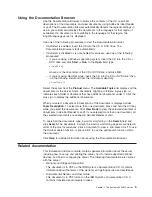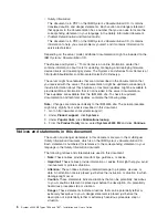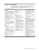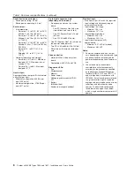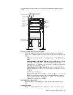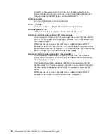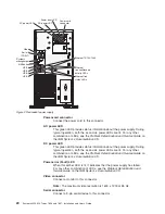
Rear view
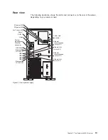
The following illustration shows the LEDs and connectors on the rear of the server,
depending on your server model.
Video
Power cord
connector
Serial 1
(COM 1)
USB 4
USB 3
USB 2
USB 1
System
management
Ethernet
connector
Ethernet 1
10/100/1000
Ethernet 2
10/100/1000
NMI button
Ethernet
transmit/receive
activity LED
Ethernet link
status LED
Ethernet
transmit/receive
activity LED
Ethernet link
status LED
AC power LED
DC power LED
Fault (error) LED
Figure 1. Fixed power supply
Chapter 1. The System x3400 M2 server
19
Summary of Contents for 783722U
Page 1: ...System x3400 M2 Types 7836 and 7837 Installation and User s Guide...
Page 2: ......
Page 3: ...System x3400 M2 Types 7836 and 7837 Installation and User s Guide...
Page 8: ...vi System x3400 M2 Types 7836 and 7837 Installation and User s Guide...
Page 18: ...xvi System x3400 M2 Types 7836 and 7837 Installation and User s Guide...
Page 57: ...Chapter 2 Installing optional devices 39...
Page 122: ...104 System x3400 M2 Types 7836 and 7837 Installation and User s Guide...
Page 153: ......
Page 154: ...Part Number 69Y4170 Printed in USA 1P P N 69Y4170...

