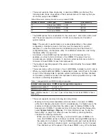
- Channel 2, DIMM connectors 7, 8, 15, and 16 are not used in
memory-mirroring mode.
- The maximum available memory is reduced to half of the installed memory
when memory mirroring is enabled. For example, if you install 48 GB of
memory, only 24 GB of addressable memory is available when you use
memory mirroring.
The following table lists the usable DIMM connectors on each memory channel.
Table 8. Connectors on each memory channel
Memory channel
DIMM connectors
Channel 0
2, 3, 10, 11
Channel 1
5, 6, 13, 14
Channel 2
7, 8, 15, 16
The following table lists the installation sequence for installing DIMMs in
memory-mirroring mode.
Table 9. Memory-mirroring mode DIMM population sequence
DIMMs
Number of installed
microprocessors
DIMM connector
First pair of DIMMs
1
3, 6
Second pair of DIMMs
1
2, 5
Third pair of DIMMs
2
11, 14
Fourth pair of DIMMs
2
10, 13
Note:
DIMM connectors 7, 8, 15, and 16 are not used in memory-mirroring mode and DIMM
connectors 1, 4, 9, and 12 are not functional on this server. Do not install DIMMs in these
connectors.
v
When you install or remove DIMMs, the server configuration information
changes. When you restart the server, the system displays a message that
indicates that the memory configuration has changed.
Attention:
Static electricity that is released to internal server components when
the server is powered-on might cause the server to stop, which could result in the
loss of data. To avoid this potential problem, always use an electrostatic-discharge
wrist strap or other grounding system when working inside the server with the
power on.
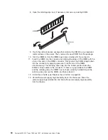
To install a DIMM, complete the following steps:
1. Read the safety information that begins on page vii and “Installation guidelines”
on page 32.
2. Turn off the server and peripheral devices, and disconnect the power cords
and all external cables.
3. Unlock the left-side cover.
4. Remove the left-side cover (see “Removing the left-side cover” on page 36).
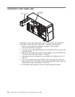
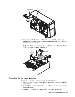
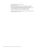
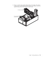
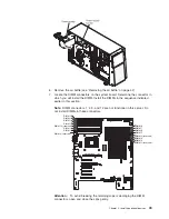
5. Rotate the power-supply cage assembly out of the chassis. Lift up the
power-supply cage handle and pull the power-supply cage assembly all the
way up until the retainer latch locks the cage in place on the chassis.
48
System x3400 M2 Types 7836 and 7837: Installation and User’s Guide
Summary of Contents for 783722U
Page 1: ...System x3400 M2 Types 7836 and 7837 Installation and User s Guide...
Page 2: ......
Page 3: ...System x3400 M2 Types 7836 and 7837 Installation and User s Guide...
Page 8: ...vi System x3400 M2 Types 7836 and 7837 Installation and User s Guide...
Page 18: ...xvi System x3400 M2 Types 7836 and 7837 Installation and User s Guide...
Page 57: ...Chapter 2 Installing optional devices 39...
Page 122: ...104 System x3400 M2 Types 7836 and 7837 Installation and User s Guide...
Page 153: ......
Page 154: ...Part Number 69Y4170 Printed in USA 1P P N 69Y4170...

