
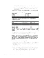
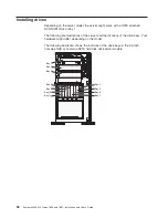
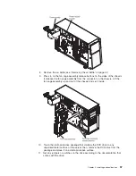
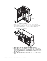
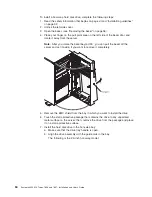
6. Remove the air baffle (see “Removing the air baffle” on page 42).
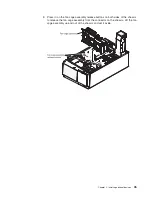
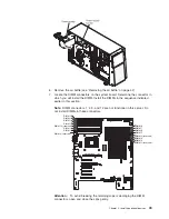
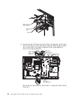
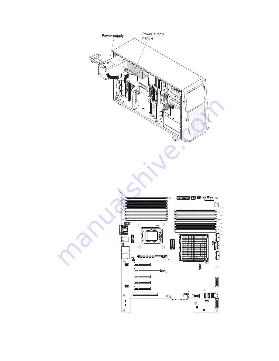
7. Locate the DIMM connectors on the system board. Determine the connector in
which you will install the DIMM. Install the DIMMs in the sequence indicated
earlier in this section.
Note:
DIMM connectors 1, 4, 9, and 12 are not functional in this server. Do
not install DIMMs in these connectors.
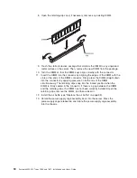
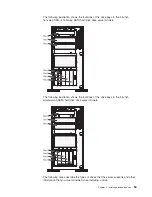
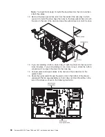
DIMM 16
DIMM 15
DIMM 14
DIMM 13
DIMM 12 (reserved)
DIMM 11
DIMM 10
DIMM 9 (reserved)
DIMM 8
DIMM 7
DIMM 6
DIMM 5
DIMM 4 (reserved)
DIMM 3
DIMM 2
DIMM 1 (reserved)
Do not insert a memory DIMM in this connector. This DIMM slot is not supported in this model.
Do not insert a memory DIMM in this connector. This DIMM slot is not supported in this model.
Do not insert a memory DIMM in this connector. This DIMM slot is not supported in this model.
Do not insert a memory DIMM in this connector. This DIMM slot is not supported in this model.
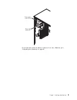
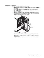
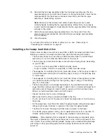
Attention:
To avoid breaking the retaining clips or damaging the DIMM
connectors, open and close the clips gently.
Chapter 2. Installing optional devices
49
Summary of Contents for 783722U
Page 1: ...System x3400 M2 Types 7836 and 7837 Installation and User s Guide...
Page 2: ......
Page 3: ...System x3400 M2 Types 7836 and 7837 Installation and User s Guide...
Page 8: ...vi System x3400 M2 Types 7836 and 7837 Installation and User s Guide...
Page 18: ...xvi System x3400 M2 Types 7836 and 7837 Installation and User s Guide...
Page 57: ...Chapter 2 Installing optional devices 39...
Page 122: ...104 System x3400 M2 Types 7836 and 7837 Installation and User s Guide...
Page 153: ......
Page 154: ...Part Number 69Y4170 Printed in USA 1P P N 69Y4170...


