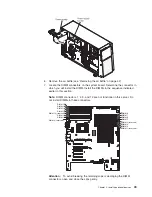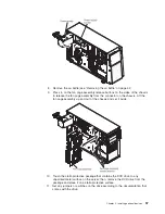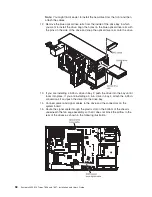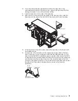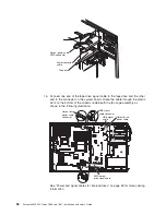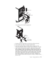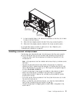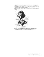
16. Reinstall the fan cage assembly. Align the fan cage assembly over the fan
cage assembly slot and with the connector on the system board. Lower the fan
cage assembly into the chassis and press down firmly until the fan cage
assembly is seated firmly in place.
Note:
Make sure that all wires and cables inside the server are routed
correctly before installing the fan cage assembly. Wiring that is not properly
routed could be damaged or might prevent the fan cage assembly from seating
properly in the server.
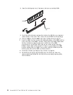
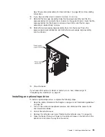
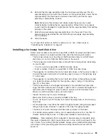
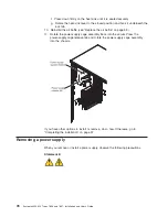
17. Rotate the power-supply cage assembly back into the server. Press the
power-supply cage release tab and rotate the power-supply cage assembly
into the chassis.
18. Close the bezel.
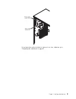
If you have other options to install or remove, do so now; otherwise go to
“Completing the installation” on page 97.
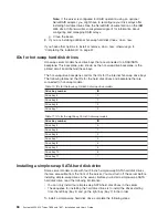
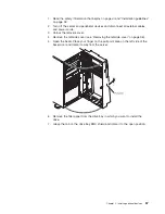
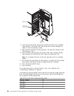
Installing a hot-swap hard disk drive
Some server models come with hot-swap SAS or SATA hot-swap hard disk drives.
Before you install a hot-swap hard disk drive, read the following information:
v
The hot-swap drives must be either all SAS hard disk drives or all SATA hard
disk drives; do not mix SAS and SATA drives in the server.
v
The hot-swap hard disk drive models come with the following drives (depending
on your model):
– Four 3.5-inch hot-swap SAS or SATA hard disk drives
– Eight or sixteen 2.5-inch hot-swap SAS or SATA hard disk drives
v
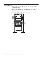
The sequence for installing the 3.5-inch hard disk drives in the four-bay models is
to install the drives starting from the left bay (bay 4) and go to the right bay (bay
7) in that order.
v
The sequence for installing the 2.5-inch hard disk drives in the eight-bay models
is to install the drives starting from the right bay (bay 4) and go to the left bay
(bay 11) in that order.
v
The hot-swap drives are arranged horizontally in the standard hard disk drive
cage; the drive numbers are 0 through 7 (right to left) on models with eight hard
disk drives and 8 through 15 (right to left) on servers with 16 hard disk drives.
When you install hard disk drives, start with drive 0.
v
Inspect the drive tray for signs of damage.
v
Make sure that the drive is correctly installed in the tray.
v
You do not have to turn off the server to install hot-swap drives in the hot-swap
drive bays.
v
All hot-swap drives must have the same throughput speed rating; mixing speed
ratings might cause all drives to operate at the lower throughput speed.
v
The drive ID for each hot-swap hard disk drive is printed on the bezel.
v
To maintain proper system cooling, do not operate the server for more than 10
minutes without either a drive or a filler panel installed in each drive bay.
Attention:
Static electricity that is released to internal server components when
the server is powered-on might cause the server to stop, which could result in the
loss of data. To avoid this potential problem, always use an electrostatic-discharge
wrist strap or other grounding system when working inside the server with the
power on.
Chapter 2. Installing optional devices
63
Summary of Contents for 783722U
Page 1: ...System x3400 M2 Types 7836 and 7837 Installation and User s Guide...
Page 2: ......
Page 3: ...System x3400 M2 Types 7836 and 7837 Installation and User s Guide...
Page 8: ...vi System x3400 M2 Types 7836 and 7837 Installation and User s Guide...
Page 18: ...xvi System x3400 M2 Types 7836 and 7837 Installation and User s Guide...
Page 57: ...Chapter 2 Installing optional devices 39...
Page 122: ...104 System x3400 M2 Types 7836 and 7837 Installation and User s Guide...
Page 153: ......
Page 154: ...Part Number 69Y4170 Printed in USA 1P P N 69Y4170...

