


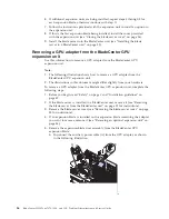


6.
If you have not already done so, touch the static-protective package that
contains the GPU adapter to any
unpainted
metal surface of the BladeCenter
unit or any
unpainted
metal surface on any other grounded rack-component
for at least 2 seconds.
7.
Remove the GPU adapter from its static-protective package.
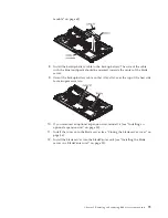
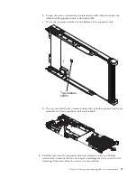
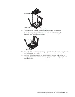
8.
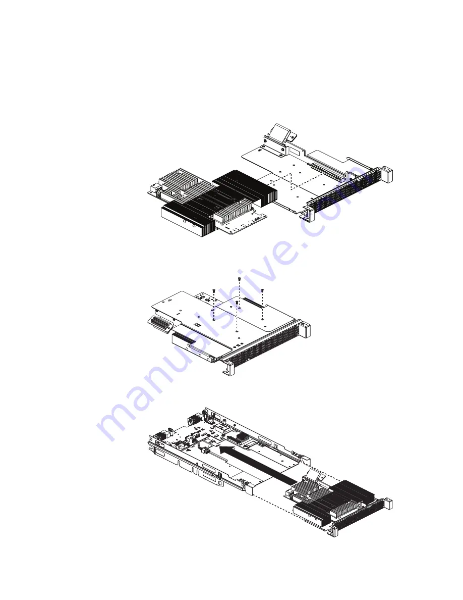
Connect the GPU adapter to the PCI connector in the expansion-unit riser
assembly, as shown in the following illustration.
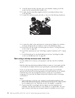
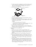
9.
Carefully turn over the expansion-unit riser assembly, and use a Phillips
screwdriver to install the four non-captive retaining screws, as shown in the
following illustration.
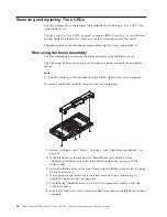
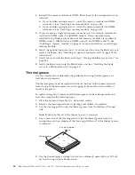
10.
Turn over the expansion-unit riser assembly and install the riser assembly into
the expansion unit system board, as shown in the following illustration.
Chapter 5. Removing and replacing blade server components
89
Summary of Contents for 7870B4U
Page 1: ...BladeCenter HS22 Type 7870 1936 and 1911 Problem Determination and Service Guide...
Page 2: ......
Page 3: ...BladeCenter HS22 Type 7870 1936 and 1911 Problem Determination and Service Guide...
Page 14: ...xii BladeCenter HS22 Type 7870 1936 and 1911 Problem Determination and Service Guide...
Page 20: ...6 BladeCenter HS22 Type 7870 1936 and 1911 Problem Determination and Service Guide...
Page 34: ...20 BladeCenter HS22 Type 7870 1936 and 1911 Problem Determination and Service Guide...
Page 248: ...234 BladeCenter HS22 Type 7870 1936 and 1911 Problem Determination and Service Guide...
Page 252: ...238 BladeCenter HS22 Type 7870 1936 and 1911 Problem Determination and Service Guide...
Page 260: ...246 BladeCenter HS22 Type 7870 1936 and 1911 Problem Determination and Service Guide...
Page 266: ...252 BladeCenter HS22 Type 7870 1936 and 1911 Problem Determination and Service Guide...
Page 267: ......
Page 268: ...Part Number 90Y5614 Printed in USA 1P P N 90Y5614...


