


v
Follow the suggested actions in the order in which they are listed in the Action column until the problem is
solved.
v
See Chapter 4, “Parts listing,” on page 41 to determine which components are customer replaceable units
(CRU) and which components are field replaceable units (FRU).
v
If an action step is preceded by “(Trained service technician only),” that step must be performed only by a
Trained service technician.
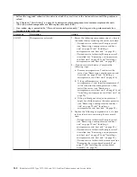
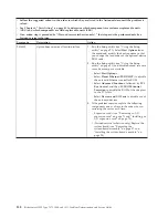
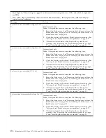
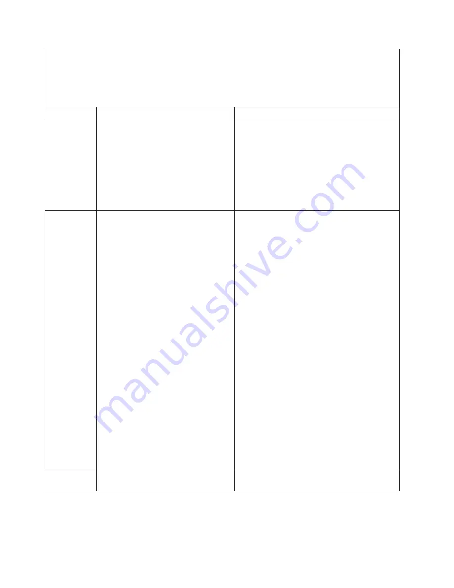
Error code
Description
Action
3008003
Firmware corrupt.
1.
Run the Setup utility (see “Using the Setup
utility” on page 21). Select
Load Default Settings
and save the settings.
2.
Follow the UEFI recovery procedure in
“Recovering from a UEFI update failure” on page
223.
3.
(Trained service technician only) Replace the
system board (see “Removing the system-board
assembly” on page 97 and “Installing the
system-board assembly” on page 98)
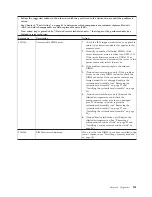
3008004
Three boot failure.
1.
Run the Setup utility (see “Using the Setup
utility” on page 21). Select
Load Default Settings
and save the settings.
2.
Update the firmware to the latest level (see
“Firmware updates” on page 34for more
information).
3.
Reseat the following components one at a time in
the order shown, restarting the server each time:
v
Battery (see “Removing the battery” on page
58 and “Installing the battery” on page 60).
v
(Trained service technician only)
Microprocessor (see “Removing a
microprocessor and heat sink” on page 90 and
“Installing a microprocessor and heat sink” on
page 94).
4.
Replace the following components one at a time
in the order shown, restarting the server each
time:
v
Battery (see “Removing the battery” on page
58 and “Installing the battery” on page 60).
v
(Trained service technician only)
Microprocessor (see “Removing a
microprocessor and heat sink” on page 90 and
“Installing a microprocessor and heat sink” on
page 94).
v
(Trained service technician only) System board
(see “Removing the system-board assembly”
on page 97 and “Installing the system-board
assembly” on page 98).
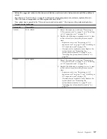
3048005
Booted secondary (backup) UEFI image.
Set SW1–4 and SW1–5 to the primary position (see
“System-board switches” on page 16).
162
BladeCenter HS22 Type 7870, 1936, and 1911: Problem Determination and Service Guide
Summary of Contents for 7870B4U
Page 1: ...BladeCenter HS22 Type 7870 1936 and 1911 Problem Determination and Service Guide...
Page 2: ......
Page 3: ...BladeCenter HS22 Type 7870 1936 and 1911 Problem Determination and Service Guide...
Page 14: ...xii BladeCenter HS22 Type 7870 1936 and 1911 Problem Determination and Service Guide...
Page 20: ...6 BladeCenter HS22 Type 7870 1936 and 1911 Problem Determination and Service Guide...
Page 34: ...20 BladeCenter HS22 Type 7870 1936 and 1911 Problem Determination and Service Guide...
Page 248: ...234 BladeCenter HS22 Type 7870 1936 and 1911 Problem Determination and Service Guide...
Page 252: ...238 BladeCenter HS22 Type 7870 1936 and 1911 Problem Determination and Service Guide...
Page 260: ...246 BladeCenter HS22 Type 7870 1936 and 1911 Problem Determination and Service Guide...
Page 266: ...252 BladeCenter HS22 Type 7870 1936 and 1911 Problem Determination and Service Guide...
Page 267: ......
Page 268: ...Part Number 90Y5614 Printed in USA 1P P N 90Y5614...