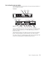
The command-line interface provides direct access to server management
functions through the IPMI 2.0 protocol. Use the command-line interface to issue
commands to control the server power, view system information, and identify the
server. You can also save one or more commands as a text file and run the file
as a script.
v
Serial over LAN
Establish a Serial over LAN (SOL) connection to manage servers from a remote
location. You can remotely view and change the UEFI settings, restart the server,
identify the server, and perform other management functions. Any standard Telnet
client application can access the SOL connection.
Using the USB memory key for VMware hypervisor
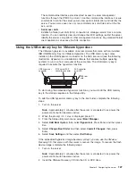
The VMware hypervisor is available on server models that come with an installed
IBM USB Memory Key for VMware Hypervisor. The USB memory key comes
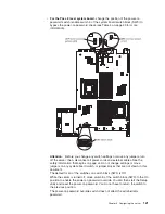
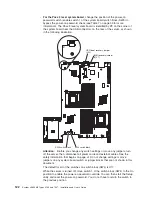
installed in the USB hypervisor connector on the SAS riser card (see the following
illustration). Hypervisor is virtualization software that enables multiple operating
systems to run on a host computer at the same time. The USB memory key is
required to activate the hypervisor functions.
USB hypervisor
connector
PCI Express SAS
controller connector
SAS controller
error LED
SAS riser
card
To start using the embedded hypervisor functions, you must add the USB memory
key to the startup sequence in the Setup utility.
To add the USB hypervisor memory key to the boot order, complete the following
steps:
1. Turn on the server.
Note:
Approximately 3 minutes after the server is connected to ac power, the
power-control button becomes active.
2. When the prompt
<F1> Setup
is displayed, press F1.
3. From the Setup utility main menu, select
Boot Manager
.
4. Select
Add Boot Option
; then, select
Hypervisor
. Press Enter, and then press
Esc.
5. Select
Change Boot Order
and then select
Commit Changes
; then, press
Enter.
6. Select
Save Settings
and then select
Exit Setup
.
If the embedded hypervisor image becomes corrupt, you can use the
VMware
Recovery
CD that comes with the server to recover the image. To recover the flash
device image, complete the following steps:
1. Turn on the server.
Note:
Approximately 3 minutes after the server is connected to ac power, the
power-control button becomes active.
2. Insert the
VMware Recovery
CD into the CD or DVD drive.
Chapter 3. Configuring the server
127
Summary of Contents for 7947E3U
Page 1: ......
Page 2: ......
Page 3: ...System x3650 M2 Types 4199 and 7947 Installation and User s Guide...
Page 8: ...vi System x3650 M2 Types 4199 and 7947 Installation and User s Guide...
Page 16: ...xiv System x3650 M2 Types 4199 and 7947 Installation and User s Guide...
Page 40: ...24 System x3650 M2 Types 4199 and 7947 Installation and User s Guide...
Page 150: ...134 System x3650 M2 Types 4199 and 7947 Installation and User s Guide...
Page 168: ...152 System x3650 M2 Types 4199 and 7947 Installation and User s Guide...
Page 169: ......
Page 170: ...Part Number 81Y6111 Printed in USA 1P P N 81Y6111...

