background image

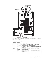
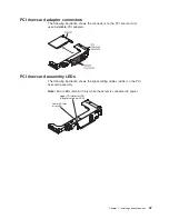
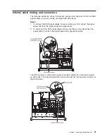
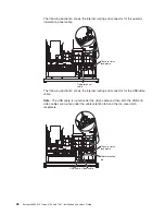
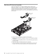
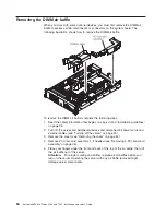
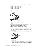
The following illustration shows the internal routing and connector for the operator
information panel cable.

Operator panel
cable

Top cover latch
receptacle

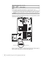
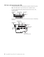
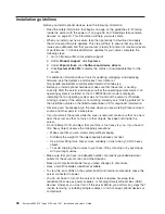
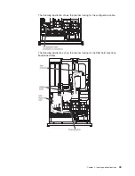
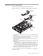
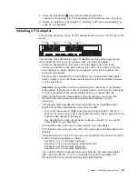
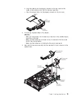
The following illustration shows the internal routing and connector for the USB/video
cable.

Note:

The USB cable is routed under the video cable and then both the USB and

video cables are routed under the cable retention tab and the top cover latch
receptacle.

USB cable Video cable

Top cover latch
receptacle

Cable retention
tab

42

System x3650 M2 Types 4199 and 7947: Installation and User’s Guide

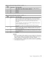
Summary of Contents for 7947E3U

Page 1: ......

Page 2: ......

Page 3: ...System x3650 M2 Types 4199 and 7947 Installation and User s Guide...

Page 4: ...the IBM Safety Information Environmental Notices and User Guide and the Warranty and Support Information documents on the Documentation CD Eighth Edition September 2010 Copyright IBM Corporation 2010...

Page 5: ...ly LEDs 37 Installation guidelines 38 System reliability guidelines 39 Working inside the server with the power on 39 Handling static sensitive devices 40 Internal cable routing and connectors 41 Remo...

Page 6: ...backup server firmware 123 Using the ServerGuide Setup and Installation CD 123 ServerGuide features 124 Setup and configuration overview 124 Typical operating system installation 125 Installing your o...

Page 7: ...Canada 143 Australia and New Zealand Class A statement 143 United Kingdom telecommunications safety requirement 143 European Union EMC Directive conformance statement 143 Germany Class A statement 14...

Page 8: ...vi System x3650 M2 Types 4199 and 7947 Installation and User s Guide...

Page 9: ...tuotteen lue turvaohjeet kohdasta Safety Information Avant d installer ce produit lisez les consignes de s curit Vor der Installation dieses Produkts die Sicherheitshinweise lesen Prima di installare...

Page 10: ...ent is labeled Statement 1 translations for that caution statement are in the Safety Information document under Statement 1 Be sure to read all caution and danger statements in this document before yo...

Page 11: ...quipment when there is evidence of fire water or structural damage v Disconnect the attached power cords telecommunications systems networks and modems before you open the device covers unless instruc...

Page 12: ...battery replace it only with the same module type made by the same manufacturer The battery contains lithium and can explode if not properly used handled or disposed of Do not v Throw or immerse into...

Page 13: ...he device v Use of controls or adjustments or performance of procedures other than those specified herein might result in hazardous radiation exposure DANGER Some laser products contain an embedded Cl...

Page 14: ...vice and the power switch on the power supply do not turn off the electrical current supplied to the device The device also might have more than one power cord To remove all electrical current from th...

Page 15: ...parts contact a service technician Statement 12 CAUTION The following label indicates a hot surface nearby Statement 26 CAUTION Do not place any object on top of rack mounted devices This server is s...

Page 16: ...xiv System x3650 M2 Types 4199 and 7947 Installation and User s Guide...

Page 17: ...chitecture technologies which help increase performance and reliability For more information see What your server offers on page 8 and Reliability availability and serviceability features on page 11 Y...

Page 18: ...ion To check for updates complete the following steps Note Changes are made periodically to the IBM Web site Procedures for locating firmware and documentation might vary slightly from what is describ...

Page 19: ...rdware and software requirements The IBM Documentation CD requires the following minimum hardware and software v Microsoft Windows XP Windows 2000 or Red Hat Linux v 100 MHz microprocessor v 32 MB of...

Page 20: ...ars are listed in order of the most occurrences Click a document to view it and press Crtl F to use the Acrobat search function or press Alt F to use the xpdf search function within the document Click...

Page 21: ...operating systems The System x and xSeries Tools Center is at http publib boulder ibm com infocenter toolsctr v1r0 index jsp The server might have features that are not described in the documentation...

Page 22: ...to you A danger statement is placed just before the description of a potentially lethal or extremely hazardous procedure step or situation Features and specifications The following information is a s...

Page 23: ...agement presence through an optional virtual media key v One Broadcom dual port 10 100 1000 Ethernet controller with Wake on LAN support and TCP IP Offload Engine TOE support v Four Ethernet ports two...

Page 24: ...s as well as UEFI compliant adapters Note The server does not support DOS v Integrated management module The integrated management module IMM combines service processor functions video controller and...

Page 25: ...and service processors The diagnostic programs create a merged log that includes events from all collected logs The information is collected into a file that you can send to IBM service and support A...

Page 26: ...port connection to a 10 Mbps 100 Mbps or 1000 Mbps network For more information see Configuring the Gigabit Ethernet controller on page 130 v Large data storage and hot swap capability The server supp...

Page 27: ...ty v TCP IP offload engine TOE support The Ethernet controllers in the server support TOE which is a technology that offloads the TCP IP flow from the microprocessors and I O subsystem to increase the...

Page 28: ...ystems in a heterogeneous environment By using industry standards IBM Systems Director supports multiple operating systems and virtualization technologies in IBM and non IBM x86 platforms Through a si...

Page 29: ...r Server controls LEDs and power This section describes the controls and light emitting diodes LEDs and how to turn the server on and off Front view The following illustration shows the controls conne...

Page 30: ...perator information panel on page 15 Rack release latches Press these latches to release the server from the rack Optional CD DVD eject button Press this button to release a CD or DVD from the CD RW D...

Page 31: ...his LED lights the Ethernet icon v Ethernet activity LEDs When any of these LEDs is lit it indicates that the server is transmitting to or receiving signals from the Ethernet LAN that is connected to...

Page 32: ...is corrected the server is restarted or a new problem occurs By placing the system error LED indicator in Remind mode you acknowledge that you are aware of the last failure but will not take immediat...

Page 33: ...d rear of the server can be used simultaneously Note The maximum video resolution is 1600 x 1200 at 75 MHz Systems management Ethernet connector Use this connector to connect the server to a network f...

Page 34: ...anel is also lit to help isolate the error This LED is the same as the system error LED on the front of the server Locator LED Use this LED to visually locate the server among other servers You can us...

Page 35: ...g power supply problems see the Problem Determination and Service Guide The following table describes the problems that are indicated by various combinations of the power supply LEDs and the power on...

Page 36: ...the power supply Off On On Faulty power supply Replace the power supply On Off Off Power supply not fully seated faulty system board or faulty power supply 1 Trained service technician only Reseat th...

Page 37: ...ower supply Replace the power supply On Off Off Power supply not fully seated faulty system board or faulty power supply 1 Trained service technician only Reseat the power supply 2 If a power channel...

Page 38: ...er While the server remains connected to power one or more fans might continue to run To remove all power from the server you must disconnect it from the power source Important To view the error LEDs...

Page 39: ...ld the power control button for more than 4 seconds to turn off the server v The IMM can turn off the server as an automatic response to a critical system failure v You can turn off the server through...

Page 40: ...24 System x3650 M2 Types 4199 and 7947 Installation and User s Guide...

Page 41: ...led instructions for installing optional hardware devices in the server Server components The following illustrations show the major components in the server Note The illustrations in this document mi...

Page 42: ...System board internal connectors The following illustration shows the internal connectors on the system board 26 System x3650 M2 Types 4199 and 7947 Installation and User s Guide...

Page 43: ...System board external connectors The following illustration shows the external input output connectors on the system board Chapter 2 Installing optional devices 27...

Page 44: ...the switch blocks The functions of the switch blocks on each of these system boards differs depending on the level of the system board that is installed in the server The following sections describe t...

Page 45: ...rver is turned on This can cause an unpredictable problem The following table describes the functions of the SW3 switch block on the Pass 8 system board Table 4 Pass 8 level system board SW3 switch de...

Page 46: ...page 40 and Turning off the server on page 22 2 Any system board switch or jumper blocks that are not shown in the illustrations in this document are reserved Pass 9 level system board If the server...

Page 47: ...umper number Jumper name Jumper setting J29 UEFI boot recovery jumper v Pins 1 and 2 Normal default Loads the primary server firmware formerly called BIOS ROM page v Pins 2 and 3 Loads the secondary b...

Page 48: ...rned on alters which flash ROM page is loaded Do not change the jumper pin position after the server is turned on This can cause an unpredictable problem The following illustration shows the jumper se...

Page 49: ...s switch does not affect the administrator password check if an administrator password is set See Passwords on page 120 for additional information about the power on password 2 Off Power on override W...

Page 50: ...ress see System board LEDs for the location of these LEDs Table 8 System pulse LEDs LED Description Action Enclosure manager heartbeat Indicates the status of power on and power off sequencing When th...

Page 51: ...and then flashes slowly to indicate that the IMM if fully operational and you can press the power control button to start the server If the LED does not begin flashing within 30 seconds of when the s...

Page 52: ...llowing illustration USB hypervisor connector PCI Express SAS controller connector SAS controller error LED SAS riser card A tape enabled model server contains the riser card that is shown in the foll...

Page 53: ...e PCI adapters PCI riser card assembly LEDs The following illustration shows the light emitting diodes LEDs on the PCI riser card assembly Note Error LEDs remain lit only while the server is connected...

Page 54: ...is not working correctly see Solving problems in the Installation Guide on the IBM Documentation CD for diagnostic information v Observe good housekeeping in the area where you are working Place remov...

Page 55: ...front of the fans For proper cooling and airflow replace the server cover before you turn on the server Operating the server for extended periods of time more than 30 minutes with the server cover rem...

Page 56: ...one is available Always use an electrostatic discharge wrist strap or other grounding system when working inside the server with the power on v Handle the device carefully holding it by its edges or...

Page 57: ...you first connect the signal cable and then the power cable and signal cable 2 To disconnect the SAS signal cables make sure that you first disconnect the power cable and then the signal cable and con...

Page 58: ...tration shows the internal routing and connector for the USB video cable Note The USB cable is routed under the video cable and then both the USB and video cables are routed under the cable retention...

Page 59: ...ng illustration shows the internal routing for the configuration cable The following illustrations show the internal routing for the SAS hard disk drive backplane cables Chapter 2 Installing optional...

Page 60: ...was not found but the server is otherwise working correctly If the server is not working correctly see the Problem Determination and Service Guide for diagnostic information To remove the cover compl...

Page 61: ...lock Note You can reach the cables on the rear of the server when the server is in the locked position 5 Press the blue latch 1 on the end of the cover release latch and lift the cover release latch...

Page 62: ...er card assemblies that you can use with the server To remove the riser card assembly complete the following steps 1 Read the safety information that begins on page vii and Installation guidelines on...

Page 63: ...in other procedures 4 Align the PCI riser card assembly with the selected PCI riser connector on the system board v PCI riser connector 1 Carefully fit the two alignment slots on the side of the asse...

Page 64: ...page 38 2 Turn off the server and peripheral devices and disconnect all power cords and external cables see Turning off the server on page 22 3 Remove the cover see Removing the cover on page 44 4 Rem...

Page 65: ...ed 3 Remove the cover see Removing the cover on page 44 4 Align the tab on the left side of the microprocessor 2 air baffle with the slot in the right side of the power supply cage 5 Lower the micropr...

Page 66: ...peripheral devices and disconnect all power cords and external cables see Turning off the server on page 22 3 Remove the cover see Removing the cover on page 44 4 Remove PCI riser card assembly 1 if...

Page 67: ...ables are disconnected 3 Remove the cover see Removing the cover on page 44 4 Make sure that PCI riser card assembly 1 is removed see Removing a PCI riser card assembly on page 46 5 Align the DIMM air...

Page 68: ...d assembly 5 Press the bracket tab 3 and slide the bracket to the right until it clicks into place 6 Return to the adapter installation instructions Storing the full length adapter bracket If you are...

Page 69: ...the cluster solution before you update the code v Some high performance video adapters are supported by your server See http www ibm com servers eserver serverproven compat us for more information v...

Page 70: ...44 4 Determine which expansion slot you will use for the adapter 5 If you are installing an adapter in PCI expansion slot 1 or 2 remove PCI riser card assembly 1 if you are installing an adapter in PC...

Page 71: ...es to the adapter Attention v When you route cables do not block any connectors or the ventilated space around any of the fans v Make sure that cables are not routed on top of components that are unde...

Page 72: ...onfiguration tasks that are required for the adapter If you have other devices to install or remove do so now Otherwise go to Completing the installation on page 111 Removing a PCI adapter To remove a...

Page 73: ...rs and pull the adapter from the PCI expansion slot If you have other devices to install or remove do so now Otherwise go to Completing the installation on page 111 Installing an IBM Virtual Media Key...

Page 74: ...g the installation on page 111 Installing a hard disk drive The following notes describe the type of hard disk drives that the server supports and other information that you must consider when you ins...

Page 75: ...rient the drive as shown in the illustration b Make sure that the tray handle is open c Align the drive assembly with the guide rails in the bay d Gently push the drive assembly into the bay until the...

Page 76: ...d disk drive See the RAID documentation on the IBM ServeRAID Support CD for information about RAID controllers If you have other devices to install or remove do so now Otherwise go to Completing the i...

Page 77: ...illustration 4 Make sure that the tray handle is open 5 Align the drive assembly with the guide rails in the bay 6 Gently push the drive assembly into the bay until the drive stops 7 Push the tray ha...

Page 78: ...40 2 Press up on the release latch at the top of the drive front 3 Rotate the handle on the drive downward to the open position 4 Pull the simple swap drive assembly out of the bay approximately 25 mm...

Page 79: ...illustration If the tape drive comes with a metal spacer attached remove the spacer before you install the tape drive on the tray 5 Prepare the drive according to the instructions that come with the...

Page 80: ...rd and controller assembly see Installing the SAS riser card and controller assembly on page 94 Fold the excess length of the cables under the SAS controller assembly 11 Slide the tape drive assembly...

Page 81: ...der card v Four hard disk drive bay filler panels v SAS controller front retention bracket v Remote battery cable interposer card and screw To install a 4 disk drive optional expansion device in a 12...

Page 82: ...S signal cables connected to the hard disk drive backplanes 8 Remove the SAS controller assembly from the server then remove the SAS controller from the SAS riser card See Removing a ServeRAID SAS con...

Page 83: ...retention bracket from the server 10 Connect one end of the internal power cable that comes with the 4 Pac HDD option kit into the empty hot swap SAS SATA power connector on the system board Chapter...

Page 84: ...ration cable a From backplane 1 disconnect the following cables in the order listed v Power cable 1 v SAS signal cable 2 v Configuration cable 3 b Lift backplane 1 out of the server by pulling it towa...

Page 85: ...tion kit to new hard disk drive backplane 3 2 c Connect the configuration cable to backplane 3 3 d Angle the new backplane and place the bottom edge into the slots for backplane 3 on the chassis next...

Page 86: ...2 to backplane 1 c Reconnect the configuration cable 3 to backplane 1 d Angle the backplane and place the bottom edge into the slots for backplane 1 on the chassis e Rotate the backplane upright so t...

Page 87: ...16 Remove the fillers if they are installed from the three connectors on the SAS expander card that comes with the option kit SAS expander card SAS expander card filler 17 Install the SAS expander car...

Page 88: ...ard snaps closed 18 If a battery and battery carrier are attached to the SAS controller that you removed in step 8 disconnect the battery carrier cable from the battery and remove the three screws tha...

Page 89: ...hat it aligns with the hole in the ServeRAID controller and position the interposer card connector over the SAS controller connector c Press the interposer card down onto the interposer card connector...

Page 90: ...roller as shown in the illustration b Align the metal bracket so that the tabs are on the back side of the SAS controller and the holes on the tabs align with the holes on the SAS controller c From th...

Page 91: ...a ServeRAID MR10i SAS SATA Controller this connector is closest to the edge of the controller and has two straight connectors Note If you are connecting the shorter SAS signal cable to a ServeRAID BR...

Page 92: ...onnect the free end of the remote battery cable to the battery on the remote battery tray For more information see Installing a ServeRAID SAS controller battery on the remote battery tray on page 100...

Page 93: ...em 30 Insert the hard disk drives and the fillers the rest of the way into the bays If you have other devices to install or remove do so now Otherwise go to Completing the installation on page 111 Cha...

Page 94: ...the most current level of server firmware and many other code updates for your server complete the following steps 1 Go to http www ibm com systems support 2 Under Product support click System x 3 Un...

Page 95: ...microprocessor complete the following steps 1 Read the safety information that begins on page vii and Installation guidelines on page 38 2 Turn off the server and disconnect all power cords and exter...

Page 96: ...n the microprocessor contacts such as oil from your skin can cause connection failures between the contacts and the socket v Handle the microprocessor carefully Dropping the microprocessor during inst...

Page 97: ...rotective cover from the bottom of the heat sink c Align the heat sink above the microprocessor with the thermal grease side down d Slide the rear flange of the heat sink into the opening in the retai...

Page 98: ...wipe the thermal grease from the bottom of the heat exchanger Note Make sure that all of the thermal grease is removed 4 Use a clean area of the cleaning pad to wipe the thermal grease from the microp...

Page 99: ...or correcting code ECC See http www ibm com servers eserver serverproven compat us for a list of supported memory modules for the server v The server supports a maximum of 16 single rank or dual rank...

Page 100: ...nk and dual rank DDR3 DIMM speed as it relates to the number of DIMMs in a channel When you install 1 DIMM per channel the memory runs at 1333 MHz When you install 2 DIMMs per channel the memory runs...

Page 101: ...roring feature consider the following information v When you use memory mirroring you must install a pair of DIMMs at a time One DIMM must be in channel 0 and the mirroring DIMM must be in the same co...

Page 102: ...connectors 1 2 3 4 5 6 7 and 8 are associated with microprocessor 1 socket CPU1 The numbers within the boxes indicate the installation sequence of the DIMM pairs For example the first DIMM pair indic...

Page 103: ...sed in memory mirroring mode When you install or remove DIMMs the server configuration information changes When you restart the server the system displays a message that indicates that the memory conf...

Page 104: ...e slots at the ends of the DIMM connector Firmly press the DIMM straight down into the connector by applying pressure on both ends of the DIMM simultaneously The retaining clips snap into the locked p...

Page 105: ...to the device The device also might have more than one power cord To remove all electrical current from the device ensure that all power cords are disconnected from the power source 1 2 Statement 8 CA...

Page 106: ...on guidelines on page 38 2 Remove the power supply blank from the empty power supply bay by pinching the side clip and pulling the power supply blank from the bay Save the power supply blank in case y...

Page 107: ...e error LED on the power supply is not lit and that the dc power LED and ac power LED on the power supply are lit indicating that the power supply is operating correctly If you have other devices to i...

Page 108: ...ent fan ready to install as soon as you remove the failed fan To install any of the three replaceable fans complete the following steps 1 Read the safety information that begins on page vii and Instal...

Page 109: ...y from the server complete the steps for the applicable server model v 12 drive capable server model 1 Press the assembly release latch toward the rear of the server and lift that end of the SAS contr...

Page 110: ...ver Installing the SAS riser card and controller assembly To install the SAS riser card and controller assembly in the server complete the steps for the applicable server model v 12 drive capable serv...

Page 111: ...ention bracket from the server b Remove the rear controller retention bracket located in the battery bay above the power supplies by pulling up the release tab 1 and sliding the bracket outward 2 Chap...

Page 112: ...sliding the bracket inward 1 and pressing down the release tab into place 2 2 Place the front end of the SAS controller in the front retention bracket and align the SAS riser card with the SAS riser c...

Page 113: ...n a dedicated slot on the SAS riser card Important If you have installed a SAS expander card in a 12 drive capable server the SAS controller is installed in a PCI riser card assembly and is installed...

Page 114: ...er see Removing the SAS riser card and controller assembly on page 93 12 drive capable server model Tape enabled server model 7 Pull the SAS controller horizontally out of the connector on the SAS ris...

Page 115: ...nstructed in the documentation that comes with the SAS controller or the battery 4 If the new SAS controller is a different physical size than the SAS controller that you removed you might have to mov...

Page 116: ...the server you are given the opportunity to import the existing RAID configuration to the new ServeRAID SAS controller Installing a ServeRAID SAS controller battery on the remote battery tray The Int...

Page 117: ...iffer slightly from your hardware 7 Install the interposer card on the interposer card connector on the ServeRAID controller a Remove the interposer card and the loose screw from the bag b Rotate the...

Page 118: ...remote battery cable into the connector 9 Install the ServeRAID controller on the riser card see Installing a PCI adapter on page 53 10 Install the PCI riser card assembly in the server see Installing...

Page 119: ...hes the posts on the battery and battery carrier c Press the posts into the rings and underneath the tabs on the remote battery tray d Secure the battery to the tray with the battery retention clip 13...

Page 120: ...he power supply see the illustration detail 14 To install another ServeRAID controller remote battery in the server repeat steps 7 on page 101 through 12 on page 103 15 Install the server cover 16 Con...

Page 121: ...ferent position to accommodate the dimensions of the current SAS ServeRAID controller complete the following steps 1 Read the safety information that begins on page vii and Installation guidelines on...

Page 122: ...ly b Rotate the bracket so that the bracket posts align with the holes in the SAS riser card assembly c Press the posts through the holes in the SAS riser card until they click into place d Install th...

Page 123: ...e cover see Removing the cover on page 44 4 Locate the SAS riser card assembly which is near the left front corner of the server 5 Push the blue locking collar on the USB hypervisor connector on the S...

Page 124: ...d assembly which is near the left front corner of the server 5 Push the blue locking collar on the USB hypervisor connector back toward the SAS riser card to unlock it from the connector 6 Pull the hy...

Page 125: ...For more information see Turning off the server on page 22 and Removing the cover on page 44 3 Attach the rubber stopper on the location as shown in the illustration Rubber stopper Ethernet adapter c...

Page 126: ...apter with the adapter connector on the system board then tilt the adapter so that the port connectors on the adapter line up with the port openings on the chassis 10 Slide the port connectors on the...

Page 127: ...you have other devices to install or remove do so now Otherwise go to Completing the installation Completing the installation To complete the installation complete the following steps 1 If you removed...

Page 128: ...2 Place the cover release latch in the open up position 3 Insert the bottom tabs of the top cover into the matching slots in the server chassis 4 Press down on the cover release latch to slide the cov...

Page 129: ...nstructions It might be easier for you to route cables before you connect the devices to the server Cable identifiers are printed on the cables that come with the server and optional devices Use these...

Page 130: ...east one multi core microprocessor which enables the server to operate as a symmetric multiprocessing SMP server You might have to upgrade the operating system to support SMP For more information see...

Page 131: ...the IMM see Using the integrated management module on page 126 v VMware embedded USB hypervisor The VMware embedded USB hypervisor is available on the server models that come with an installed IBM USB...

Page 132: ...s Use the ASU program online or out of band to modify UEFI settings from the command line without the need to restart the server to access the Setup utility For more information about using this progr...

Page 133: ...sion and date v System Settings Select this choice to view or change the server component settings Processors Select this choice to view or change the processor settings Memory Select this choice to v...

Page 134: ...mation about the adapters and drivers in the server that are compliant with EFI 1 10 and UEFI 2 0 v Network Select this choice to view or configure the network options such as the iSCSI PXE and networ...

Page 135: ...event log Also after you complete a repair or correct an error clear the system event log to turn off the system error LED on the front of the server POST Event Viewer Select this choice to enter the...

Page 136: ...ssword for a system administrator you must type the power on password to complete the system startup A system administrator who types the administrator password has access to the full Setup utility me...

Page 137: ...on that begins on page vii Do not change settings or move jumpers on any system board switch or jumper blocks that are not shown in this document The default for all of the switches on switch block SW...

Page 138: ...ion Before you change any switch settings or move any jumpers turn off the server then disconnect all power cords and external cables See the safety information that begins on page vii Do not change s...

Page 139: ...ea for the server firmware This is a secondary copy of server firmware that you update only during the process of updating server firmware If the primary copy of the server firmware becomes damaged us...

Page 140: ...d runs the SAS RAID configuration program with LSI chip sets for ServeRAID adapters only v Checks the microcode firmware levels of a ServeRAID adapter and determines whether a later level is available...

Page 141: ...he server model service processor hard disk drive controllers and network adapters Then the program checks the CD for newer device drivers This information is stored and then passed to the operating s...

Page 142: ...icroprocessor and restarts with the one good microprocessor v NMI detection and reporting v Automatic Server Restart ASR when POST is not complete or the operating system hangs and the OS watchdog tim...

Page 143: ...B memory key is required to activate the hypervisor functions USB hypervisor connector PCI Express SAS controller connector SAS controller error LED SAS riser card To start using the embedded hypervis...

Page 144: ...ing functions v Remotely viewing video with graphics resolutions up to 1600 x 1200 at 75 MHz regardless of the system state v Remotely accessing the server using the keyboard and mouse from a remote c...

Page 145: ...ess from the server UEFI or from your network administrator The Login page is displayed 2 Type the user name and password If you are using the IMM for the first time you can obtain the user name and p...

Page 146: ...this program as described in this document v Use the LSI Configuration Utility program to perform the following tasks Perform a low level format on a hard disk drive Create an array of hard disk drive...

Page 147: ...you must type the administrator password to access the full Setup utility menu If you do not type the administrator password a limited Setup utility menu is available 3 Select System Settings Adapter...

Page 148: ...UEFI settings from the command line without the need to restart the server to access the Setup utility You can also use the ASU program to configure the optional remote presence features or other IMM...

Page 149: ...dates and interim fixes complete the following steps 1 Make sure that you have run the Discovery and Inventory collection tasks 2 On a system that is connected to the Internet go to http www ibm com e...

Page 150: ...134 System x3650 M2 Types 4199 and 7947 Installation and User s Guide...

Page 151: ...gnostic tests that you can perform Most systems operating systems and programs come with documentation that contains troubleshooting procedures and explanations of error messages and error codes If yo...

Page 152: ...he U S and Canada call 1 800 IBM SERV 1 800 426 7378 Hardware service and support You can receive hardware service through your IBM reseller or IBM Services To locate a reseller authorized by IBM to p...

Page 153: ...s or implied warranties in certain transactions therefore this statement may not apply to you This information could include technical inaccuracies or typographical errors Changes are periodically mad...

Page 154: ...r DVD drive speed is the variable read rate Actual speeds vary and are often less than the possible maximum When referring to processor storage real and virtual storage or channel volume KB stands for...

Page 155: ...ures is a customer responsibility Table 14 Limits for particulates and gases Contaminant Limits Particulate v The room air must be continuously filtered with 40 atmospheric dust spot efficiency MERV 9...

Page 156: ...ances as applicable throughout the European Union This label is applied to various products to indicate that the product is not to be thrown away but rather reclaimed upon end of life per this Directi...

Page 157: ...to your call For Taiwan Please recycle batteries For the European Union Notice This mark applies only to countries within the European Union EU Batteries or packaging for batteries are labeled in acc...

Page 158: ...of their waste For California Perchlorate material special handling may apply See http www dtsc ca gov hazardouswaste perchlorate The foregoing notice is provided in accordance with California Code o...

Page 159: ...l interference and 2 this device must accept any interference received including interference that may cause undesired operation Industry Canada Class A emission compliance statement This Class A digi...

Page 160: ...eingebaut werden EN 55022 Klasse A Ger te m ssen mit folgendem Warnhinweis versehen werden Warnung Dieses ist eine Einrichtung der Klasse A Diese Einrichtung kann im Wohnbereich Funk St rungen verursa...

Page 161: ...ions Japan Electronics and Information Technology Industries Association JEITA statement Japanese Electronics and Information Technology Industries Association JEITA Confirmed Harmonics Guideline prod...

Page 162: ...Taiwan Class A compliance statement 146 System x3650 M2 Types 4199 and 7947 Installation and User s Guide...

Page 163: ...6 CD RW DVD drive installing 111 CD DVD drive activity LED 14 CD DVD eject button 14 Class A electronic emission notice 143 components server 25 configuration updating server 114 115 with ServerGuide...

Page 164: ...p 135 gigabit Ethernet controller configuring 130 grease thermal 82 H hard disk drive formatting 131 installing 58 60 removing 60 62 hardware service and support 136 heat output 7 help getting 135 hot...

Page 165: ...gement systems 8 memory 10 memory mirroring description 85 DIMM population sequence 87 memory module installing 87 memory module continued specifications 7 menu choices in Setup utility 117 microproce...

Page 166: ...ration updating 114 115 server firmware starting backup 123 server firmware UEFI compliant 8 server power and IMM 21 ServeRAID support 11 ServerGuide downloading CD 10 features 124 using 123 using to...

Page 167: ...figuration 114 115 USB connector 13 17 USB hypervisor memory key installing 107 removing 108 using 127 using boot selection menu program 123 embedded hypervisor 127 LSI Configuration Utility 130 remot...

Page 168: ...152 System x3650 M2 Types 4199 and 7947 Installation and User s Guide...

Page 169: ......

Page 170: ...Part Number 81Y6111 Printed in USA 1P P N 81Y6111...

Reviews: