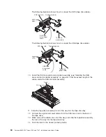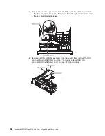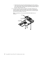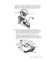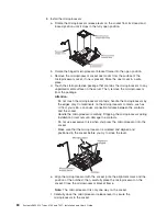
b. Connect the straight connector end of the longer SAS signal cable to the
other SAS connector that is labeled “Ports 3-0” on a ServeRAID-MR10i
SAS/SAS Controller. This cable has a right-angle connector and a straight
connector.
Note:
If you are connecting the longer SAS signal cable to a
ServeRAID-BR10i SAS/SATA Controller, the connectors are reversed. You
must connect the straight connector end of the longer SAS signal cable to
the connector that is labeled “Port 0–3”.
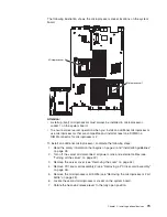
23. Remove the PCI riser-card assembly (see “Removing a PCI riser-card
assembly” on page 46).
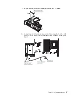
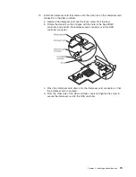
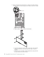
24. Orient the SAS controller so that the connectors are on the underside of the
controller. Install the SAS controller in the connector on the PCI riser card.
(See the previous illustration and see “Installing a PCI adapter” on page 53.)
25. Install the PCI riser-card assembly in the server (see “Installing a PCI
riser-card assembly” on page 47).
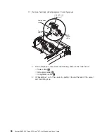
26. Connect the free end of the remote battery cable to the battery on the remote
battery tray. For more information, see “Installing a ServeRAID SAS controller
battery on the remote battery tray” on page 100.
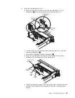
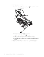
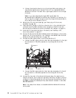
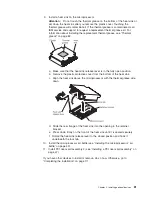
27. Connect the SAS signal cables to the SAS expander card:
a. Connect the SAS signal cable from hard disk drive backplane 2 to the right
front connector on the SAS expander card (as facing the front of the
server).
SAS signal cables
SAS expander
card
Backplanes 1 - 3
b. Connect the SAS signal cable from hard disk drive backplane 3 to the left
front connector on the SAS expander card (as facing the front of the
server).
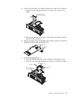
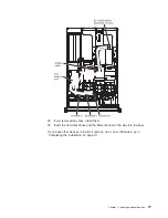
28. Connect the loose end of the shorter SAS signal cable (this cable has two
straight connectors and is already connected to the SAS controller) to the rear
connector on the SAS expander card. Route the cable through the left side of
the DIMM air baffle and underneath the cable retention features on the baffle.
See the illustration.
Note:
The cables that connect to a ServeRAID-BR10i SAS/SATA Controller
are reversed.
76
System x3650 M2 Types 4199 and 7947: Installation and User’s Guide
Summary of Contents for 7947E3U
Page 1: ......
Page 2: ......
Page 3: ...System x3650 M2 Types 4199 and 7947 Installation and User s Guide...
Page 8: ...vi System x3650 M2 Types 4199 and 7947 Installation and User s Guide...
Page 16: ...xiv System x3650 M2 Types 4199 and 7947 Installation and User s Guide...
Page 40: ...24 System x3650 M2 Types 4199 and 7947 Installation and User s Guide...
Page 150: ...134 System x3650 M2 Types 4199 and 7947 Installation and User s Guide...
Page 168: ...152 System x3650 M2 Types 4199 and 7947 Installation and User s Guide...
Page 169: ......
Page 170: ...Part Number 81Y6111 Printed in USA 1P P N 81Y6111...

