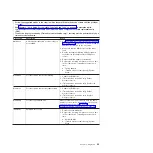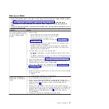
Universal
Serial
Bus
(USB)
port
problems
v
Follow
the
suggested
actions
in
the
order
in
which
they
are
listed
in
the
Action
column
until
the
problem
is
solved.
v
See
to
determine
which
components
are
customer
replaceable
units
(CRU)
and
which
components
are
field
replaceable
units
(FRU).
v
If
an
action
step
is
preceded
by
“(Trained
service
technician
only),”
that
step
must
be
performed
only
by
a
trained
service
technician.
Symptom
Action
A
USB
device
does
not
work.
1.
Make
sure
that:
v
The
correct
USB
device
driver
is
installed.
v
The
operating
system
supports
USB
devices.
2.
Make
sure
that
the
USB
configuration
options
are
set
correctly
in
the
Configuration/Setup
Utility
program
menu
(see
the
User’s
Guide
for
more
information).
3.
If
you
are
using
a
USB
hub,
disconnect
the
USB
device
from
the
hub
and
connect
it
directly
to
the
server.
4.
Move
the
device
cable
to
a
different
USB
connector.
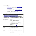
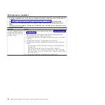
Video
problems
See
Light
path
diagnostics
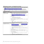
Light
path
diagnostics
is
a
system
of
LEDs
on
various
external
and
internal
components
of
the
server.
When
an
error
occurs,
LEDs
are
lit
throughout
the
server.
By
viewing
the
LEDs
in
a
particular
order,
you
can
often
identify
the
source
of
the
error.
When
LEDs
are
lit
to
indicate
an
error,
they
remain
lit
when
the
server
is
turned
off,
provided
that
the
server
is
still
connected
to
power
and
the
power
supply
is
operating
correctly.
Before
you
work
inside
the
server
to
view
light
path
diagnostics
LEDs,
read
the
safety
information
that
begins
on
page
and
If
an
error
occurs,
view
the
light
path
diagnostics
LEDs
in
the
following
order:
1.
Look
at
the
operator
information
panel
on
the
front
of
the
server.
v
If
the
information
LED
is
lit,
it
indicates
that
information
about
a
suboptimal
condition
in
the
server
is
available
in
the
BMC
system
event
log
or
in
the
system
event/error
log.
v
If
the
system-error
LED
is
lit,
it
indicates
that
an
error
has
occurred;
go
to
step
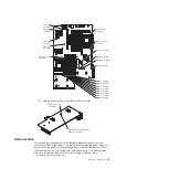
The
following
illustration
shows
the
operator
information
panel.
Chapter
3.
Diagnostics
49
Summary of Contents for 7985
Page 1: ...IBM System x3655 Type 7985 and 7943 Problem Determination and Service Guide...
Page 2: ......
Page 3: ...IBM System x3655 Type 7985 and 7943 Problem Determination and Service Guide...
Page 8: ...vi IBM System x3655 Type 7985 and 7943 Problem Determination and Service Guide...
Page 18: ...xvi IBM System x3655 Type 7985 and 7943 Problem Determination and Service Guide...
Page 36: ...18 IBM System x3655 Type 7985 and 7943 Problem Determination and Service Guide...
Page 110: ...92 IBM System x3655 Type 7985 and 7943 Problem Determination and Service Guide...
Page 112: ...View 1...
Page 159: ...Battery Chapter 5 Removing and replacing server components 141...
Page 202: ...184 IBM System x3655 Type 7985 and 7943 Problem Determination and Service Guide...
Page 212: ...194 IBM System x3655 Type 7985 and 7943 Problem Determination and Service Guide...
Page 217: ......
Page 218: ...Part Number 42D2167 Printed in USA 1P P N 42D2167...

