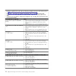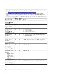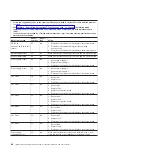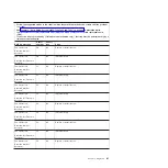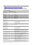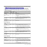
v
Follow
the
suggested
actions
in
the
order
in
which
they
are
listed
in
the
Action
column
until
the
problem
is
solved.
v
See
to
determine
which
components
are
customer
replaceable
units
(CRU)
and
which
components
are
field
replaceable
units
(FRU).
v
If
an
action
step
is
preceded
by
“(Trained
service
technician
only),”
that
step
must
be
performed
only
by
a
trained
service
technician.
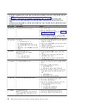
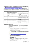
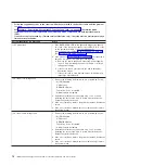
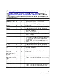
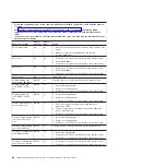
BMC
log
message
Sensor
number
Sensor
type
Action
VRD
1.2V
Assertion
01
(Power
unit
failure)
2F
08
1.
(Trained
service
technician
only)
Replace
the
system
board.
2.
(Trained
service
technician
only)
Isolate
the
failing
microprocessor.
3.
(Trained
service
technician
only)
Replace
the
microprocessor.
Ambient
temperature
32
01
Make
sure
that
the
fans
have
good
airflow
and
are
not
obstructed.
Exhaust
temperature
33
01
Make
sure
that
the
fans
have
good
airflow
and
are
not
obstructed.
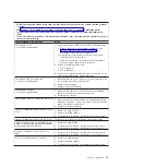
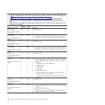
Power
supply
1
fault
38
08
1.
Reseat
power
supply
1.
2.
Replace
power
supply
1.
3.
(Trained
service
technician
only)
Replace
the
system
board.
Power
supply
2
fault
39
08
1.
Reseat
power
supply
2.
2.
Replace
power
supply
2.
3.
(Trained
service
technician
only)
Replace
the
system
board.
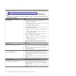
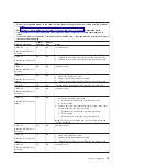
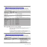
Fan
1
tach
40
04
1.
Reseat
fan
1.
2.
Replace
fan
1.
3.
(Trained
service
technician
only)
Replace
the
system
board.
Fan
2
tach
41
04
1.
Reseat
fan
2.
2.
Replace
fan
2.
3.
Replace
the
front
fan
board.
4.
(Trained
service
technician
only)
Replace
the
system
board.
Fan
3
tach
42
04
1.
Reseat
fan
3.
2.
Replace
fan
3.
3.
Replace
the
front
fan
board.
4.
(Trained
service
technician
only)
Replace
the
system
board.
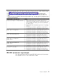
Fan
4
tach
43
04
1.
Reseat
fan
4.
2.
Replace
fan
4.
3.
(Trained
service
technician
only)
Replace
the
system
board.
Fan
5
tach
44
04
1.
Reseat
fan
5.
2.
Replace
fan
5.
3.
(Trained
service
technician
only)
Replace
the
system
board.
Fan
6
tach
45
04
1.
Reseat
fan
6.
2.
Replace
fan
6.
3.
(Trained
service
technician
only)
Replace
the
system
board.
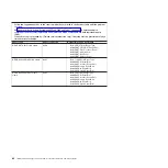
Power
supply
configuration
error
4F
0A
Make
sure
that
the
power
supplies
are
installed
in
the
correct
order
and
that
the
power
supplies
are
operating
properly.
80
IBM
System
x3655
Type
7985
and
7943:
Problem
Determination
and
Service
Guide
Summary of Contents for 7985
Page 1: ...IBM System x3655 Type 7985 and 7943 Problem Determination and Service Guide...
Page 2: ......
Page 3: ...IBM System x3655 Type 7985 and 7943 Problem Determination and Service Guide...
Page 8: ...vi IBM System x3655 Type 7985 and 7943 Problem Determination and Service Guide...
Page 18: ...xvi IBM System x3655 Type 7985 and 7943 Problem Determination and Service Guide...
Page 36: ...18 IBM System x3655 Type 7985 and 7943 Problem Determination and Service Guide...
Page 110: ...92 IBM System x3655 Type 7985 and 7943 Problem Determination and Service Guide...
Page 112: ...View 1...
Page 159: ...Battery Chapter 5 Removing and replacing server components 141...
Page 202: ...184 IBM System x3655 Type 7985 and 7943 Problem Determination and Service Guide...
Page 212: ...194 IBM System x3655 Type 7985 and 7943 Problem Determination and Service Guide...
Page 217: ......
Page 218: ...Part Number 42D2167 Printed in USA 1P P N 42D2167...

