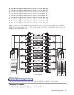
6.
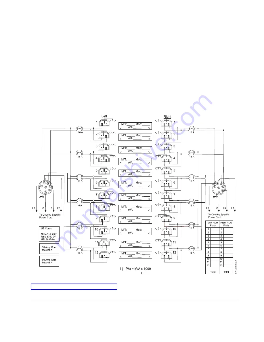
Connect next highest power drawer to outlet 7 on circuit breaker 4.
7.
Connect next highest power drawer to outlet 9 on circuit breaker 5.
8.
Connect next highest power drawer to outlet 11 on circuit breaker 6.
9.
Connect next highest power drawer to outlet 12 on circuit breaker 6.
10.
Connect next highest power drawer to outlet 10 on circuit breaker 5.
11.
Connect next highest power drawer to outlet 8 on circuit breaker 4.
12.
Connect next highest power drawer to outlet 6 on circuit breaker 3.
13.
Connect next highest power drawer to outlet 4 on circuit breaker 2.
14.
Connect next highest power drawer to outlet 2 on circuit breaker 1.
Following these rules allow the load to be distributed more evenly across the six PDU circuit breakers.
Ensure that your total power load is below the maximum that is listed in the table and that each circuit
breaker is not loaded above 16 A.
Related concepts
:
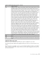
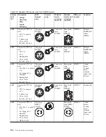
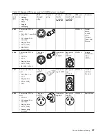
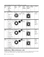
“Supported PDU power cords” on page 105
Find out which power distribution unit (PDU) power cords are supported for your system.
Planning for cables
Learn how to develop plans for cabling your server and devices.
Site and hardware planning
119
Summary of Contents for 8408-44E
Page 1: ...Power Systems Site and hardware planning IBM...
Page 2: ......
Page 3: ...Power Systems Site and hardware planning IBM...
Page 16: ...xiv Site and hardware planning...
Page 18: ...2 Site and hardware planning...
Page 22: ...6 Site and hardware planning...
Page 51: ...Figure 19 Model 0555 and 7014 S25 plan view Site and hardware planning 35...
Page 192: ...176 Site and hardware planning...
Page 204: ...188 Site and hardware planning...
Page 205: ......
Page 206: ...IBM Printed in USA...

