background image

Model 7965-S42 supported feature codes:

Learn about the supported feature codes that are available for 7965-S42 racks.

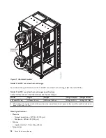
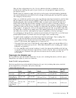
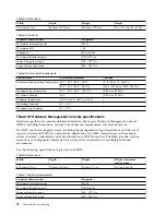
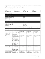
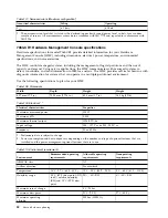
Feature code (FC) ECRK

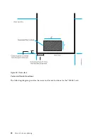
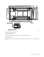
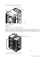
FC ECRK is an optional rear rack extender that can be used for 7965-S42 racks. This extender is installed
on the rear of the 7965-S42 rack and provides 130 mm (5 in.) of extra space to hold cables on the side of
the rack and to keep the center area clear for cooling and service access. Two extenders can be stacked to
provide 260mm (10 in.) of additional rear cabling space. The extender has hook-and-loop fasteners to
secure cables.

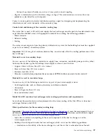
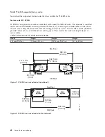
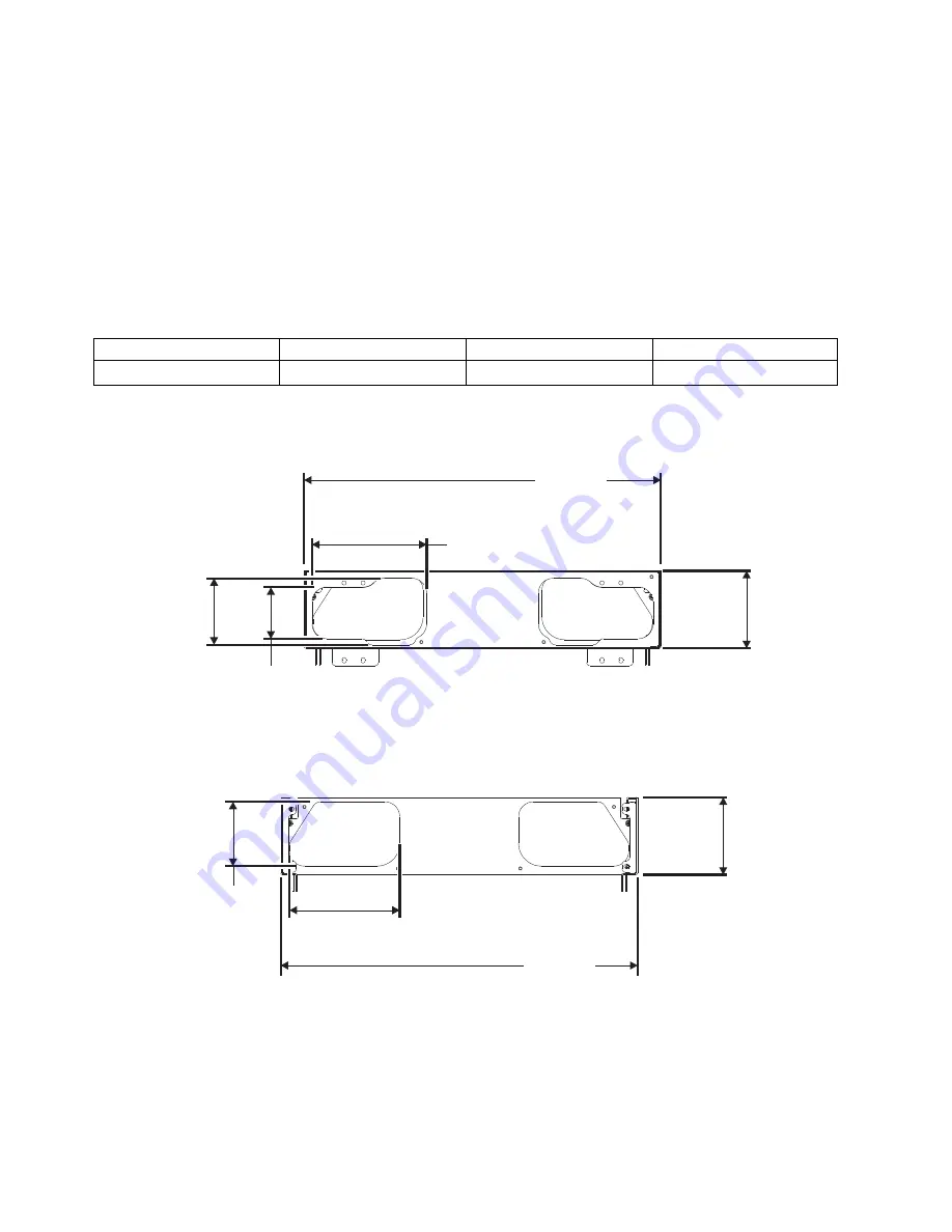
Table 87. Dimensions for FC ECRK rear rack extender

Width

Depth

Height

Weight

600 mm (23.62 in.)

130 mm (5.11 in.)

1952.4 mm (76.87 in.)

14.5 kg (32 lbs)

600 mm

(23.6 in)

130 mm

(5.12 in)

192.5 mm

(7.58 in)

111.6 mm

(4.39 in)

86.3 mm

(3.4 in)

Cable

Egress

Cable

Egress

S42 Rack

Rear Door

P8HAD506-0

Figure 41. FC ECRK rear rack extender (top cable exit)
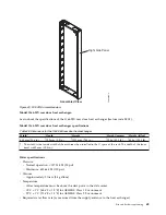
600 mm

(23.6 in)

130 mm

(5.12 in)

108 mm

(4.25 in)

185 mm

(7.3 in)

Cable

Egress

Cable

Egress

S42 Rack

Rear Door

P8HAD507-0

Figure 42. FC ECRK rear rack extender (bottom cable exit)

68

Site and hardware planning

Summary of Contents for 8408-44E

Page 1: ...Power Systems Site and hardware planning IBM...

Page 2: ......

Page 3: ...Power Systems Site and hardware planning IBM...

Page 4: ...Notices manual G229 9054 and the IBM Environmental Notices and User Guide Z125 5823 This edition applies to IBM Power Systems servers that contain the POWER8 processor and to all associated models Cop...

Page 5: ...53 rack 40 7014 T00 7014 T42 and 0553 supported feature codes 44 7014 T00 7014 T00 and 0553 racks multiple attachment 46 7014 T00 7014 T42 and 0553 rack weight distribution and floor loading 46 Planni...

Page 6: ...5 7014 7953 and 7965 racks 111 Calculating the power load for 7188 or 9188 power distribution units 117 Planning for cables 119 Cable management 120 Power cord routing and retention 121 Planning for s...

Page 7: ...tional copies of safety information documentation can be obtained by calling the IBM Hotline at 1 800 300 8751 German safety information Das Produkt ist nicht f r den Einsatz an Bildschirmarbeitspl tz...

Page 8: ...evices To Disconnect 1 Turn off everything unless instructed otherwise 2 For AC power remove the power cords from the outlets 3 For racks with a DC power distribution panel PDP turn off the circuit br...

Page 9: ...mperatures will exceed the manufacturer s recommended ambient temperature for all your rack mounted devices v Do not install a unit in a rack where the air flow is compromised Ensure that air flow is...

Page 10: ...take to eliminate potential hazards v Verify that the route that you choose can support the weight of the loaded rack cabinet Refer to the documentation that comes with your rack cabinet for the weigh...

Page 11: ...DANGER Rack mounted devices are not to be used as shelves or work spaces L002 L003 1 2 or 1 2 or 1 2 3 4 or Safety notices ix...

Page 12: ...he product might be equipped with multiple AC power cords or multiple DC power cables To remove all hazardous voltages disconnect all power cords and power cables L003 L007 CAUTION A hot surface nearb...

Page 13: ...tacle Although shining light into one end and looking into the other end of a disconnected optical fiber to verify the continuity of optic fibers many not injure the eye this procedure is potentially...

Page 14: ...stand under overhanging load v Do not use on uneven surface incline or decline major ramps v Do not stack loads v Do not operate while under the influence of drugs or alcohol v Do not support ladder...

Page 15: ...ing interfaces only Type 2 or Type 4 ports as described in GR 1089 CORE and require isolation from the exposed OSP cabling The addition of primary protectors is not sufficient protection to connect th...

Page 16: ...xiv Site and hardware planning...

Page 17: ...stomer service representative will install your system unit and verify correct operation Some system units are considered customer installed If you are not sure check with your sales representative Th...

Page 18: ...2 Site and hardware planning...

Page 19: ...sible Target date Completion date Plan your office or computer room layout physical planning Prepare for power cords and electrical needs Prepare for cables and cabling Create or modify communications...

Page 20: ...lp you prepare your site for the delivery and installation of your server Information contained in the Site preparation and physical planning might be helpful for preparing your data center for the ar...

Page 21: ...limation v System air distribution Planning for the installation of rear door heat exchangers v Planning for the installation of rear door heat exchangers v Heat exchanger specifications v Water speci...

Page 22: ...6 Site and hardware planning...

Page 23: ...ances Use the following specifications to plan for your server Note Due to special safety and servicing considerations IBM does not support installation of 8408 44E or 8408 E8E server nodes higher tha...

Page 24: ...the four power supply units during normal system operation 6 When operating on only two power supplies over subscription is not available In this situation the maximum values are 3100 W 3 16 kVA and...

Page 25: ...centers that are operated at low relative humidity v Data centers that have do not have ESD floors and where people are allowed to wear non ESD shoes might want to consider increasing humidity given t...

Page 26: ...ux 15K RPM 4KN SAS HDD Gen3 ESFE 571 GB IBM i 15K RPM 4KN SAS HDD Gen3 ESFF 600 GB AIX Linux 15K RPM 4KN SAS HDD Gen3 ESFN 571 GB IBM i 15K RPM 4KN SAS HDD Gen2 S ESFP 600 GB AIX Linux 15K RPM 4KN SAS...

Page 27: ...to you and your server installation This IBM system is available with an optional acoustical door feature that can help reduce the noise that is emitted from this system The actual sound pressure leve...

Page 28: ...ce with the applicable regulations Table 9 Service clearances Clearances Front Rear Side1 Top1 Operating 762 mm 30 in 762 mm 30 in Nonoperating 762 mm 30 in 762 mm 30 in 762 mm 30 in 762 mm 30 in 1 Si...

Page 29: ...mentation on the instrumentation setup and circuits that are used for electrical testing ENERGY STAR Test Method for Computer Servers ECOVA Generalized Test Protocol for Calculating the Energy Efficie...

Page 30: ...Protocol for Calculating the Energy Efficiency of Internal Ac Dc and Dc Dc Power Supplies Expansion unit and migration tower specifications Expansion unit and migration tower specifications provide d...

Page 31: ...able 21 Service clearances for rack mounted expansion unit Front Back Sides 914 mm 36 in 914 mm 36 in 914 mm 36 in Side and top clearances are optional during operation Safety compliance This hardware...

Page 32: ...to service Table 24 Environment requirements Environment Recommended operating Allowable operating Nonoperating ASHRAE class A3 Airflow direction Front to back Temperature1 18 C 27 C 64 F 80 F 5 C 40...

Page 33: ...and 15 C 59 F dew point 12 0 C 10 4 F DP and 8 80 RH 5 80 RH Maximum dew point 24 C 75 F 27 C 80 F Maximum operating altitude 3050 m 10000 ft Shipping temperature 40 C to 60 C 40 F to 140 F Shipping r...

Page 34: ...mm 25 5 in 1020 mm 40 0 in 1800 mm 71 0 in 36 The 1 8 meter rack has 10 EIA units of space remaining This space will be filled with a 5 EIA filler panel a 3 EIA filler panel and two of the 1 EIA fille...

Page 35: ...30 in 762 mm 30 in 762 mm 30 in Side and top clearances are optional when operating Table 33 Feature code Feature Code Top rack specify Bottom rack specify PDU support Power cords 05501 None None 0 to...

Page 36: ...8 C 73 F 22 8 C 73 F Maximum altitude 3048 m 10000 ft 3048 m 10000 ft Noise emissions Rack noise levels are a function of the number and type of drawers installed See your server or hardware specific...

Page 37: ...e for the 0551 and 7014 T00 racks Feature code 6249 is available for the 0553 and 7014 T42 racks The overall sound reduction is approximately 6 dB The doors add 381 mm 15 in to the depth of the racks...

Page 38: ...5163 and 7188 7014 feature codes 7176 7177 7178 and 7188 3 If units plug into a power distribution unit PDU power jumper cord feature code 6458 6459 6095 or 9911 is required If redundant power supply...

Page 39: ...eter rack with 42 EIA units of total space The rack includes one PDU feature code 9188 9176 9177 or 9178 2 0551 0553 and 0555 feature codes 5160 5161 5163 and 7188 7014 feature codes 7176 7177 7178 an...

Page 40: ...eature code 9188 9176 9177 or 9178 4 If unit plugs into a PDU two feature code 6458 6459 6095 or 9911 power jumper cords are required Feature code 0123 5074 lower expansion unit in rack feature code 0...

Page 41: ...with 42 EIA units of total space 2 0551 0553 and 0555 feature codes 5160 5161 5163 and 7188 7014 feature codes 7176 7177 7178 and 7188 3 Feature code 0125 does not plug into a PDU Feature code 0133 M...

Page 42: ...s are required Feature code 0134 IBM service representation installation in rack feature code 0138 IBM service representation installation in rack Table 44 Feature code 0134 IBM rack Rack specify code...

Page 43: ...otal space 2 0551 0553 and 0555 feature codes 5160 5161 5163 and 7188 7014 feature codes 7176 7177 7178 and 7188 3 0578 includes two rack power cords that plug into a PDU Feature code 0588 PCI X expan...

Page 44: ...s of total space 2 0551 0553 and 0555 feature codes 5160 5161 5163 and 7188 7014 feature codes 7176 7177 7178 and 7188 3 If unit plugs into a PDU feature code 1422 is required If redundant power suppl...

Page 45: ...uency 100 127 or 200 240 V ac at 50 60 plus or minus 0 5 Hz Thermal output maximum 2560 Btu hr Power requirements maximum 750 W Power factor 0 95 Inrush current 41 A Leakage current maximum 3 5 mA Pha...

Page 46: ...ower cord exiting the bottom of the rack See model 9406 270 Cable Poster Addendum included with the 0551 model 9406 270 rack 3 The rack does not have power distribution Each model 9406 270 and 7104 re...

Page 47: ...es 915 mm 36 in 254 mm 10 in 71 mm 2 8 in Recommended minimum vertical service clearance from floor is 2439 mm 8 ft See your server or hardware specifications for specific temperature requirements and...

Page 48: ...lectrical power temperature environment and service clearances Table 57 Dimensions Dimensions Properties Height 1240 mm 49 in Capacity 25 usable EIA units Height with PDP DC only Not applicable Figure...

Page 49: ...r server or hardware specifications for specific requirements Frequency Hz 50 or 60 The 7188 power distribution unit used with this rack is mounted horizontally and requires one EIA unit of space Tabl...

Page 50: ...Model 0555 and 7014 S25 rack operational clearances Figure 18 Model 0555 and 7014 S25 with stabilizer foot 34 Site and hardware planning...

Page 51: ...Figure 19 Model 0555 and 7014 S25 plan view Site and hardware planning 35...

Page 52: ...cations for the 7014 T00 and 7014 T42 or 0553 racks Model 7014 T00 rack Hardware specifications provide detailed information for your rack including dimensions electrical power temperature environment...

Page 53: ...r more information about rack weight distribution and floor loading see 7014 T00 7014 T42 and 0553 rack weight distribution and floor loading Table 61 Dimensions for doors Door model Width Height Dept...

Page 54: ...mately 381 mm 15 in to the depth of the racks Related reference 7014 T00 7014 T42 and 0553 rack weight distribution and floor loading on page 46 Racks can be heavy when populated with several drawers...

Page 55: ...er cables are typically supplied with IBM products For OEM products you must provide the applicable circuit breakers and DC power cables Note Front doors are optional on the 7014 T00 rack Figure 21 FC...

Page 56: ...or FC 6117 and FC EPB8 Environment Recommended operating Allowable operating Nonoperating Temperature 5 C to 55 C 23 F 131 F Humidity range 0 90 relative humidity RH non condensing Shipping temperatur...

Page 57: ...rforation front door and standard rear door 644 mm 25 4 in 1098 mm 43 3 in 2015 mm 79 3 in 289 kg 636 lb N A N A Rack with FC ERG7 770 780 high perforation front door and standard rear door 644 mm 25...

Page 58: ...lb With acoustic foam 16 kg 34 lb Standard side covers each 10 mm 4 in 1740 mm 68 5 in 1042 mm 41 0 in 18 lbs 8 25 kg 18 lb FC 6084 front door OEM 639 mm 25 2 in 1946 mm 76 6 in 56 mm 2 3 in 16 kg 34...

Page 59: ...ith drawer temperature requirements All rack installations require careful site and facilities planning that is designed to address both the cumulative drawer heat output and provide the airflow volum...

Page 60: ...drawers Use the Weight distribution distances for racks when loaded and Floor loading for racks when loaded tables to ensure proper floor loading and weight distribution 7014 T00 7014 T42 and 0553 sup...

Page 61: ...Figure 24 FC ERG0 rear rack extender top down view Figure 25 FC ERG0 assembled view Site and hardware planning 45...

Page 62: ...FC 6080 7014 T00 7014 T00 and 0553 racks multiple attachment 7014 T00 7014 T42 or 0553 racks can be bolted together in a multiple rack arrangement This figure shows that arrangement A kit is available...

Page 63: ...adjacent computer equipment weight distribution areas Units are inches with mm in parentheses 4 Weight distribution distance is 1 2 the service clearance values shown in the figure plus cover thicknes...

Page 64: ...8 in 138 kg 304 lb N A N A Rack with triplex doors 600 mm 23 6 in 1206 2 1228 8 mm 47 5 48 4 in 2002 mm 78 8 in 147 kg 324 lb N A N A Rack with rear door heat exchanger indicator 600 mm 23 6 in 1196...

Page 65: ...gers are on the rack Side service clearance is not required during normal operation of the rack when outriggers are not installed Rear door heat exchanger Specifications for Power orderable feature co...

Page 66: ...tions available for the 7953 94X and 7965 94Y rack Cabling within the rack Side cable channels are available in the rack to route cables There are two cable channels on each side of the rack as shown...

Page 67: ...om rear of the rack helps to route the cables leaving the rack in place This bar can be removed for installation and then reattached after the rack is installed and cabled Figure 27 Cabling within the...

Page 68: ...lizers with wheels installed on the sides of the rack cabinet The outriggers can be removed only after the rack is in the final location and will not be moved more than 2 m 6 ft away in any direction...

Page 69: ...8 in 261 kg 575 lb 42 EIA units Multiple racks Learn how to attach multiple 7953 94X and 7965 94Y racks together Multiple 7953 94X and 7965 94Y racks can be attached together via attachment brackets...

Page 70: ...h Height Weight empty Weight filled 600 mm 23 6 in 129 mm 5 0 in 1950 mm 76 8 in 39 kg 85 0 lb 48 kg 105 0 lb 1 The width is the inside width of the machine when installed in the U space of the rack T...

Page 71: ...indicates that the heat exchanger not only removed all of the heat that was generated by the devices but further cooled the air so that the average air temperature that is leaving the rack is actually...

Page 72: ...lowing problems v Leaks due to corrosion and pitting of the metal components of the heat exchanger or of the water supply system v Buildup of scale deposits inside the heat exchanger which can cause t...

Page 73: ...location v Copper v brass with less than 30 zinc content v Brass with less than 30 zinc content v Stainless steel 303 or 316 v Peroxide cured ethylene propylene diene monomer EPDM rubber non metal ox...

Page 74: ...s manifolds pumps and any other hardware that makes up the closed loop water supply system at your location v Copper v brass with less than 30 zinc content v Brass with less than 30 zinc content v Sta...

Page 75: ...stem heat exchanger supply hose and return hose excluding any reservoir tank must have a maximum 18 4 liters 4 8 gallons of water This is a cautionary statement not a functional requirement Also consi...

Page 76: ...y these quick connects can be eliminated and replaced with a hose barb connection Manifolds and piping Manifolds that accept large diameter feed pipes from a pump unit are the preferred method for spl...

Page 77: ...ondary loop Use quick connect couplings to attach the hoses to the heat exchangers Hose couplings that connect to the heat exchanger must have the following characteristics v The couplings must be con...

Page 78: ...85 lb empty 48 kg 105 lb filled High end appearance front door 590 mm 23 2 in 1942 mm 76 5 in 100 mm 3 9 in 9 1 kg 20 lb Table 83 Dimensions for side covers Width1 Depth Height Weight2 12 mm 0 5 in 1...

Page 79: ...s for rear door heat exchanger Width Depth Height Weight empty Weight filled 600 mm 23 6 in 129 mm 5 0 in 1950 mm 76 8 in 39 kg 85 lb 48 kg 105 lb For more information see Model 1164 95X rear door hea...

Page 80: ...Caster and leveler locations The following diagram provides the caster and leveler locations for the 7965 S42 rack Figure 35 Floor cutout 64 Site and hardware planning...

Page 81: ...le routing options available for the 7965 S42 rack Cabling within the rack Side cable channels are available in the rack to route cables Three cable channels are on each side of the rack Figure 36 Cas...

Page 82: ...ss openings that are on the top of the rack cabinet allow cables to be routed up and out of the rack Cable access covers on the rear are adjustable by loosening the side screws and sliding the covers...

Page 83: ...For racks that are on a 600 mm 23 6 in pitch you can use screws to clamp the racks together For racks that are on a 609 mm 24 0 in pitch two spacer brackets must be added to set the proper spacing bef...

Page 84: ...ed to provide 260mm 10 in of additional rear cabling space The extender has hook and loop fasteners to secure cables Table 87 Dimensions for FC ECRK rear rack extender Width Depth Height Weight 600 mm...

Page 85: ...chine when installed in the U space of the rack The width of the front bezel is 482 mm 19 0 in Water specifications v Pressure Normal operation 137 93 kPa 20 psi Maximum 689 66 kPa 100 psi v Volume Ap...

Page 86: ...so that the average air temperature that is leaving the rack is actually lower than air temperature that is entering the rack To help maintain optimum performance of the rear door heat exchanger and p...

Page 87: ...lowing problems v Leaks due to corrosion and pitting of the metal components of the heat exchanger or of the water supply system v Buildup of scale deposits inside the heat exchanger which can cause t...

Page 88: ...location v Copper v brass with less than 30 zinc content v Brass with less than 30 zinc content v Stainless steel 303 or 316 v Peroxide cured ethylene propylene diene monomer EPDM rubber non metal ox...

Page 89: ...s manifolds pumps and any other hardware that makes up the closed loop water supply system at your location v Copper v brass with less than 30 zinc content v Brass with less than 30 zinc content v Sta...

Page 90: ...stem heat exchanger supply hose and return hose excluding any reservoir tank must have a maximum 18 4 liters 4 8 gallons of water This is a cautionary statement not a functional requirement Also consi...

Page 91: ...y these quick connects can be eliminated and replaced with a hose barb connection Manifolds and piping Manifolds that accept large diameter feed pipes from a pump unit are the preferred method for spl...

Page 92: ...racteristics v The couplings must be constructed of passivated 300 L series stainless steel or brass with less than 30 zinc content The coupling size is 19 mm 0 75 in v The supply hose must have a Par...

Page 93: ...Nonoperating 5 2 4 8 37 33 Note 1 These levels were measured in controlled acoustical environments according to the procedures specified by the American National Standards Institute ANSI S12 10 and IS...

Page 94: ...ications Hardware specifications provide detailed information about your Hardware Management Console HMC including dimensions electrical environmental requirements and noise emissions The HMC controls...

Page 95: ...ls in a specific location might exceed the average values stated because of room reflections and other nearby noise sources The declared sound power levels indicate an upper limit below which a large...

Page 96: ...0 C 10 4 F dew point Relative humidity RH 8 85 8 85 RH 5 to 80 RH 5 100 RH Maximum dew point 24 C 75 F 27 C 80 6 F 29 C 84 2 F 29 C 84 2 F Maximum altitude 3050 m 10000 ft 3050 m 10000 ft 3050 m 10000...

Page 97: ...r consumption and heat output vary depending on the number and type of optional features that are installed and the power management optional features that are in use Table 106 Environmental requireme...

Page 98: ...te in a multiple partitioned environment Use the following specifications to plan for your HMC Table 108 Dimensions Width Depth Height Weight 437 mm 17 2 in 705 3 mm 27 76 in 43 0 mm 1 7 in 14 5 kg 32...

Page 99: ...ent regulations such as those prescribed by OSHA or European Community Directives might govern noise level exposure in the workplace and might apply to you and your server installation This IBM system...

Page 100: ...3 kg 18 3 lb Table 113 Electrical Electrical characteristics Properties Power requirements 200 W Voltage 90 264 V ac Frequency 47 63 Hz Maximum thermal output 682 4 Btu hr Phase 1 kVA 0 204 Table 114...

Page 101: ...an 65 dB G8264R RackSwitch specification sheet Hardware specifications provide detailed information for your IBM BNT RackSwitch including dimensions electrical power temperature environment and servic...

Page 102: ...humidity range non condensing 10 90 RH Maximum altitude 3050 m 10000 ft Heat dissipation 1100 Btu hr Rack installation specifications for racks not purchased from IBM Learn the requirements and speci...

Page 103: ...the overall external width of the rack There are no restrictions on the location of side walls and corner posts relative to the internal mounting space v The front rack opening must be 450 mm wide 0 7...

Page 104: ...mension C the width between the outsides of the standard mounting flanges see Figure 47 on page 89 The back rack opening must be 500 mm 19 69 in wide for dimension C the width between the outsides of...

Page 105: ...his space is necessary for cable management Note Power distribution units PDUs should be mounted horizontally in the U space so that the additional width of the rack can also be used for the 9080 MHE...

Page 106: ...t require clearance on the rear side of the rails Note If the rack or cabinet has square holes on the mounting flanges a plug in hole adapter might be required If non IBM rails are used the rails must...

Page 107: ...es of the NRTL license or certificate a CB Certificate a Letter of Authorization to apply the NRTL mark the first few pages of the NRTL certification report Listing in an NRTL publication or a copy of...

Page 108: ...ck or cabinet or any products that are installed in the cabinet had safety or weight labels that are applied by the manufacturer they must be intact and translated into the languages that are required...

Page 109: ...ular server For information on power requirements for expansion units or peripherals select the appropriate device from the list of compatible hardware specifications For equipment not listed check yo...

Page 110: ...ormation You can print the recommended power distribution wiring diagram as a reference for your electrician Server Information Form 3A Use this form to record the type and quantity of power cords tha...

Page 111: ...le length Plug type input voltage Telephone contact Licensed programs Table 125 Licensed programs list Plugs and receptacles Select the country or region link to see plugs and receptacles available by...

Page 112: ...and length IBM shipped plug Matched female wall receptacle on wall IBM part number 6460 Type 4 NEMA 5 15 plug 120 127 V ac 12 A 4 3 m 14 ft Plug type 4 Receptacle type 4 39M5513 6469 Type 5 NEMA 6 15...

Page 113: ...200 240 V ac 10 A 2 7 m 9 ft Plug type 23 Receptacle type 23 39M5151 6475 Type 79 SI 32 or Type 32 200 240 V ac 10 A 2 7 m 9 ft Plug type 32 Receptacle type 32 39M5172 6476 Type 24 1011 S24507 200 240...

Page 114: ...6488 Type 2 IRAM 2073 200 240 V ac 10 A 2 7 m 9 ft Plug type 2 Receptacle type 2 39M5068 6493 Type 62 GB 2099 1 1002 200 240 V ac 10 A 2 7 m 9 ft Plug type 62 Receptacle type 62 39M5206 6494 Type 69 I...

Page 115: ...nt Plug type 34 Receptacle type 34 73F4931 6651 Type 75 CNS 10917 3 100 127 V ac 15 A 2 7 m 9 ft Plug type 75 Receptacle type 75 39M5463 6659 Type 76 CNS 10917 3 200 240 V ac 15 A 2 7 m 9 ft Plug type...

Page 116: ...DC power cable3 4 48 V dc 25 A 3 m 10 ft Multi Beam XLX 3 position connector Two hole standard barrel lug5 00RR437 Notes 1 The part numbers that are mentioned in this table meet the European Union Dir...

Page 117: ...a Canada Cayman Islands Columbia Costa Rica Cuba Dominican Republic Ecuador El Salvador Guam Guatemala Haiti Honduras Jamaica Marshall Islands Mexico Micronesia Federal States of Montserrat Netherland...

Page 118: ...kraine Uzbekistan Vanuatu Vietnam Wallis and Futuna Western Sahara 6473 Denmark Falkland Islands Malvinas Faroe Islands 6474 Bahrain Bangladesh Bhutan Botswana British Indian Ocean Territory Brunei Da...

Page 119: ...ed Kingdom Uruguay Uzbekistan Vanuatu Vietnam Virgin Islands British Wallis and Futuna Western Sahara Yemen Zambia Zimbabwe 6491 Afghanistan Albania Algeria Andorra Angola Antarctica Antigua and Barbu...

Page 120: ...China 6494 India 6495 Brazil 6496 Korea 6497 United States Mexico 6498 Japan 6651 Taiwan 6653 Internationally available 6654 Algeria American Samoa Anguilla Antigua and Barbuda Aruba Bahamas Barbados...

Page 121: ...ico Micronesia Federated States of Moldova Republic of Monaco Mongolia Montserrat Morocco Mozambique Myanmar Namibia Nauru Nepal Netherlands Netherlands Antilles New Caledonia New Zealand Niger Nigeri...

Page 122: ...nnector type 363C6W Receptacle type 363R6W 39M5415 Europe Middle East Africa EMEA 6492 Power cord PDU to wall v 200 208 V ac or 240 V ac v 60 A plug 48 A derated v Single phase v 4 3 m 14 ft v IEC 309...

Page 123: ...da Latin America Japan and Taiwan 6656 Power cord PDU to wall v 230 V ac v 32 A v Single phase v 4 3 m 14 ft v IEC 309 P N G Plug type 332P6W Connector type 332C6W Receptacle type 332R6W 39M5414 Europ...

Page 124: ...ype 460R9W United States Canada Latin America Japan and Taiwan EPTK EPTL PDU with fixed cord v 200 208 V ac or 240 V ac v 60 A plug 48 A derated v 3 phase delta v 4 3 m 14 ft v IEC 309 3P G v Nine IEC...

Page 125: ...l of features alterations or attachments IBM will advise the customer of any limitation resulting from the alteration affecting IBM s ability to provide Warranty Service or Maintenance after review by...

Page 126: ...e ECCF Only one ECCF is allowed per server The connectors on the ECCF include a male USB and a female 9 pin D shell connector The cable length is 1650 mm 65 inches The cable can be connected to either...

Page 127: ...orizontally mounted PDUs must be used for 9080 MHE 9080 MME 9119 MHE and 9119 MME systems Vertically mounted PDUs occupy and limit access to the cable routing space on the side of the rack and cannot...

Page 128: ...9188 universal PDU Table 130 7188 or 9188 universal PDU features PDU Number Racks usage Supported power cords PDU to wall 7188 or 9188 universal PDU 7014 T00 7014 T42 7953 94X 7965 94Y 0551 0553 and...

Page 129: ...Us when the rack is populated with various server models Power distribution unit plus specifications The power distribution unit plus PDU has power monitoring capabilities The PDU is an intelligent AC...

Page 130: ...7000 ft room ambient 10 C 35 C 50 F 95 F Operating humidity 8 80 noncondensing Localized air temperature in PDU 60 C 140 F maximum Rated frequency all feature codes 50 60 Hz Circuit breakers Six doub...

Page 131: ...r temperature in PDU 60 C 140 F maximum Rated frequency all feature codes 50 60 Hz Circuit breakers Six double pole branch rated circuit breakers rated at 20 A Power outlet Six IEC 320 C19 outlets rat...

Page 132: ...ase Provided power receptacles Supported power cords PDU to wall EPTG PDU 7014 T00 and 7014 T42 racks v 200 240 V ac v Single phase or three phase1 v 16 A 24 A 32 A 48 A or 63 A1 9 IEC 320 C19 and 3 I...

Page 133: ...ated at 20 amps for 1U C19 PDU models Six double pole branch rated circuit breakers rated at 20 amps for 1U C13 PDU models The intelligent switched AC power distribution unit PDU provides the capabili...

Page 134: ...00 240 V ac single phase Souriau UTG plug type PDL plug 32 A 6658 Power cord PDU to wall 4 3 m 14 ft 200 240 V ac single phase Souriau UTG plug type KP plug 30 A 24 A derated 6667 Power cord PDU to wa...

Page 135: ...let 6 on circuit breaker 3 13 Connect next highest power drawer to outlet 4 on circuit breaker 2 14 Connect next highest power drawer to outlet 2 on circuit breaker 1 Following these rules allow the l...

Page 136: ...e management v Install and route the communications cables starting with smallest diameter first and then progressing to the largest diameter v Use the innermost cable management bridge lances for pow...

Page 137: ...system that could potentially cause system operations to stop functioning Different types of power cord retention are available Some of the most commonly used types of retention include v Cable manage...

Page 138: ...nks A port is a wide port if there are more than one SAS physical link in the port Wide ports are designed to enhance performance and provide redundancy in case an individual SAS physical link fail Th...

Page 139: ...rmation The following table contains a list of the supported serial attached SCSI SAS cable types and their designed usage Table 140 Functions for supported SAS cables Cable type Function AA cable Thi...

Page 140: ...Mini SAS HD Narrow connector attaches to a PCIe3 SAS adapter Each mini SAS connector attaches to a different SAS tape drive AS cable This 3 m 9 8 ft SAS cable is used to attach a DCS3700 to PCIe3 LP...

Page 141: ...rear bulkhead internal cable 44V5252 3669 The following table contains specific information about each supported SAS cable feature with narrow HD connectors for PCIe3 SAS adapters Table 142 Supported...

Page 142: ...nnector cable 4 m 13 1 ft 46C2900 ECBY 5507 HD SAS YE1 narrow connector cable 3 m 9 8 ft 46C2902 ECBZ 5509 HD SAS AS narrow connector cable 3 m 9 8 ft 00FW799 ECC5 1 Can be used to attach just a bunch...

Page 143: ...k expansion drawer in a cascaded configuration SAS AA cable SAS adapter to SAS adapter SAS YO cable SAS adapter to a disk expansion drawer SAS X cable Two SAS adapters to a disk expansion drawer in a...

Page 144: ...neral types of configurations that are shown in the following sections v SAS adapter to 5886 disk expansion drawers on page 129 v SAS adapter to media expansion drawer on page 132 v SAS adapter to exp...

Page 145: ...tion on page 145 SAS adapter to 5886 disk expansion drawers Figure 60 Figure 61 on page 130 Figure 62 on page 131 and Figure 63 on page 132 illustrate connecting a SAS adapter to one two three or four...

Page 146: ...Note The YO cable must be routed along the right side of the rack frame Figure 61 SAS adapter to two disk expansion drawers 130 Site and hardware planning...

Page 147: ...Note The YO cable must be routed along the right side of the rack frame Figure 62 SAS adapter to four disk expansion drawers Site and hardware planning 131...

Page 148: ...drawers can be cascaded only one level deep Note The YO cable must be routed along the right side of the rack frame SAS adapter to media expansion drawer Figure 64 on page 133 illustrates connecting a...

Page 149: ...onnecting a SAS adapter to both a disk expansion drawer and a media expansion drawer on separate adapter ports It is also possible to cascade a second disk expansion drawer see Figure 62 on page 131 F...

Page 150: ...SAS port to disk expansion drawer Figure 66 on page 135 illustrates connecting a system external SAS port to a disk expansion drawer Disk expansion drawers cannot be cascaded Figure 65 SAS adapter to...

Page 151: ...slots Figure 67 on page 136 illustrates connecting a SAS adapter to internal SAS disk slots through the system external SAS port Note Internal cable FC 3669 must be installed to enable this configurat...

Page 152: ...r can be used to attach a disk expansion or media expansion drawer as shown in Figure 60 on page 129 or Figure 64 on page 133 Figure 67 SAS adapter to internal SAS disk slots through the system extern...

Page 153: ...on page 139 Figure 71 on page 140 and Figure 72 on page 141 illustrate connecting two SAS adapters to one two or four disk expansion drawers in a RAID configuration It is also possible to connect thre...

Page 154: ...the right side of the rack frame v The X cable must be attached to the same numbered port on all adapters Figure 69 Two SAS RAID adapters to a disk expansion drawer in a multi initiator HA RAID confi...

Page 155: ...the right side of the rack frame v The X cable must be attached to the same numbered port on all adapters Figure 70 Two SAS RAID adapters to two disk expansion drawers in a multi initiator HA RAID con...

Page 156: ...he right side of the rack frame v The X cable must be attached to the same numbered port on all adapters Figure 71 Two SAS RAID adapters to four disk expansion drawers in a multi initiator HA RAID con...

Page 157: ...sk drives it is also possible to cascade a second disk expansion drawer off two out of the three drawers for a maximum of five disk expansion drawers per adapter See Figure 62 on page 131 Notes v Disk...

Page 158: ...drawer v The 5887 storage drawer is connected to same numbered port on each adapter v HD AA cable is required Figure 73 Two RAID SAS adapters with HD connectors to a disk expansion drawer in a multi...

Page 159: ...rawer v The 5887 storage drawers are connected to same numbered port on each adapter v HD AA cable is required Figure 74 Two RAID SAS adapters with HD connectors to two disk expansion drawer in a mult...

Page 160: ...7 storage drawer v The 5887 storage drawers are connected to same numbered port on each adapter Figure 75 Two RAID SAS adapters with HD connectors to three disk expansion drawers in a multi initiator...

Page 161: ...sion drawer in a unique JBOD configuration Notes v No cascading allowed for the 5887 storage drawer v The 5887 storage drawer is connected to same numbered port on each adapter v HD AA cable is requir...

Page 162: ...ernal disks in the system unit enclosure into groups that you can manage separately 1 Stop and power off the system For more information see Stopping a system or logical partition 2 Cable a single sys...

Page 163: ...imline media device in the 8247 21L 8247 22L 8284 22A 8286 41A or 8286 42A SAS cabling for the 5887 disk drive enclosure Learn about the different serial attached SCSI SAS cabling configurations avail...

Page 164: ...ables to connect to the 5887 enclosure v Supported only on AIX and Linux systems 2 Single FC 5901 or FC 5278 adapter to two 5887 enclosures via a mode 1 connection v 5887 enclosures with two sets of 2...

Page 165: ...tems 5 Two single FC 5901 or FC 5278 adapters to one 5887 enclosure via a mode 2 connection v 5887 enclosure with two sets of 12 hard disk drives HDDs v Connection using two SAS YO cables to connect t...

Page 166: ...2 hard disk drives HDDs v Connection using dual SAS X cables to connect to the 5887 enclosure v Each pair of FC 5901 adapters controls half of the 5887 enclosure v Supported only on AIX and Linux syst...

Page 167: ...7 enclosure with four sets of six hard disk drives HDDs v Connection using dual SAS X cables to connect to the 5887 enclosure v Supported only on AIX and Linux systems Figure 81 Mode 2 connection of a...

Page 168: ...connections 4 The long end 0 5 m of the YO cable must be connected to the left side of the enclosure as viewed from the rear The short end 0 25 m of the YO cable must be connected to the right side o...

Page 169: ...3 Two pairs of FC 5805 or FC 5903 adapters to one 5887 enclosure via a mode 2 connection v 5887 enclosure with 1 12 HDDs or 1 8 SSDs v Connection using dual SAS X cables to connect to the 5887 enclos...

Page 170: ...configurations with three 5887 enclosures The following list describes the supported configurations 1 Dual FC 5913 or FC ESA3 adapters to one 5887 enclosure via a mode 1 connection v 5887 enclosures...

Page 171: ...o the same port on each adapter v SAS 6x AA cable is required for connecting each pair of FC 5913 or FC ESA3 adapters v Supported only on AIX and Linux systems v No IBM i support v POWER7 only support...

Page 172: ...s with HD connectors to three 5887 enclosures via a mode 1 connection v No cascading allowed Figure 86 Mode 1 connection of two 5887 enclosures by using HD connectors to two PCIe2 SAS adapters 156 Sit...

Page 173: ...HD connectors to one 5887 enclosure via a mode 2 connection v No cascading allowed v HD AA cable is required Figure 87 Mode 1 connection of three 5887 enclosures to two PCIe2 SAS adapters with HD con...

Page 174: ...rs to one 5887 enclosure via a mode 1 connection v No cascading allowed v Two HD AA narrow cables are required Figure 88 Mode 2 connection of a 5887 enclosure by using HD connectors to two pairs of PC...

Page 175: ...ctors to two 5887 enclosures via a mode 1 connection v No cascading allowed v Two HD AA narrow cables are required Figure 89 Mode 1 connection of a 5887 enclosure to two PCIe3 SAS adapters with HD nar...

Page 176: ...ors to three 5887 enclosures via a mode 1 connection v No cascading allowed v One HD AA narrow cable is required Figure 90 Mode 1 connection of two 5887 enclosures to two PCIe3 SAS adapters with HD na...

Page 177: ...HD narrow connectors to four 5887 enclosures via a mode 1 connection v No cascading allowed Figure 91 Mode 1 connection of three 5887 enclosures to two PCIe3 SAS adapters with HD narrow connectors Si...

Page 178: ...ne 5887 enclosure via a mode 2 connection v No cascading allowed v Two HD AA narrow cables are required on each pair of adapters Figure 92 Mode 1 connection of four 5887 enclosures to two PCIe3 SAS ad...

Page 179: ...nnections v The cable that plugs into independent SAS adapter 1 C contains a label with the P1 identifier This adapter does not have access to any other independent adapter and has access only to driv...

Page 180: ...t are available for the ESLL and ESLS storage enclosures SAS adapter to the ESLL and ESLS storage enclosures The following list describes some of the supported configurations for connecting SAS adapte...

Page 181: ...nection v Connection by using SAS YO12 cables to connect to the ESLL or ESLS storage enclosure v Supported on AIX Linux and IBM i systems Figure 95 Mode 1 connection of one ESLL or ESLS storage enclos...

Page 182: ...ttach the SAS cables to the same port on both adapters v Connection by using SAS YO12 cables to connect to the ESLL or ESLS storage enclosure v Supported on AIX Linux and IBM i systems Figure 96 Mode...

Page 183: ...ach the cables to the same port on both adapters v Connection by using dual SAS YO12 cables to connect to the ESLL or ESLS storage enclosure v Supported on AIX Linux and IBM i systems Figure 97 Mode 1...

Page 184: ...nnection v Connection by using two SAS YO12 cables to connect to the ESLL or ESLS storage enclosure v Supported only on AIX and Linux systems Figure 98 Mode 1 connection of two ESLL or ESLS storage en...

Page 185: ...tion v Connection by using two SAS YO12 cables to connect to the ESLL or ESLS storage enclosure v Supported only on AIX and Linux systems Figure 99 Mode 2 connection of ESLL or ESLS storage enclosure...

Page 186: ...ust attach the cables to the same port on both adapters v Connection by using SAS X12 cables to connect to the ESLL or ESLS storage enclosure v Supported only on AIX and Linux systems Figure 100 Mode...

Page 187: ...t attach the cables to the same port on both adapters v Connection by using SAS X12 cables to connect to the ESLL or ESLS storage enclosure v Supported only on AIX and Linux systems Figure 101 Mode 2...

Page 188: ...Figure 102 Mode 4 connection of one ESLL or ESLS storage enclosure by using X12 cables to four independent SAS adapters 172 Site and hardware planning...

Page 189: ...includes I O planning Understanding workloads Learn about the different types of workloads in your environment Critical workloads These are workloads that need to be online and running during a servi...

Page 190: ...tition Mobility IBM Knowledge Center information for LPM IBM PowerVM virtualization Introduction and Configuration Redbook SG24 7940 This Redbooks publication provides an introduction to PowerVM virtu...

Page 191: ...f workload on the backup LPAR to use the PowerHA Cluster High Availability function In addition during a planned failover the workload is quiesced on the active partition and then restarted on the pas...

Page 192: ...176 Site and hardware planning...

Page 193: ...efore this statement may not apply to you This information could include technical inaccuracies or typographical errors Changes are periodically made to the information herein these changes will be in...

Page 194: ...lying on such data in sensitive or critical operations Users should periodically check IBM s support websites for updated information and fixes applicable to the system and related software Homologati...

Page 195: ...www ibm com able Privacy policy considerations IBM Software products including software as a service solutions Software Offerings may use cookies or other technologies to collect product usage informa...

Page 196: ...e radio frequency energy and if not installed and used in accordance with the instruction manual may cause harmful interference to radio communications Operation of this equipment in a residential are...

Page 197: ...ard of the VCCI Council If this equipment is used in a domestic environment radio interference may occur in which case the user may be required to take corrective actions Japan Electronics and Informa...

Page 198: ...nt People s Republic of China Declaration This is a Class A product In a domestic environment this product may cause radio interference in which case the user may need to perform practical action Elec...

Page 199: ...ustimmung von IBM ver ndert bzw wenn Erweiterungskomponenten von Fremdherstellern ohne Empfehlung von IBM gesteckt eingebaut werden EN 55022 EN 55032 Klasse A Ger te m ssen mit folgendem Warnhinweis v...

Page 200: ...stalled and used in accordance with the instructions may cause harmful interference to radio communications However there is no guarantee that interference will not occur in a particular installation...

Page 201: ...sponsibility for any failure to satisfy the protection requirements resulting from a non recommended modification of the product including the fitting of non IBM option cards European Community contac...

Page 202: ...it in den EU Mitgliedsstaatenund h lt die Grenzwerte der EN 55022 EN 55032 Klasse B ein Um dieses sicherzustellen sind die Ger te wie in den Handb chern beschrieben zu installieren und zu betreiben De...

Page 203: ...that all proprietary notices are preserved You may not distribute display or make derivative works of these publications or any portion thereof without the express consent of IBM Commercial Use You ma...

Page 204: ...188 Site and hardware planning...

Page 205: ......

Page 206: ...IBM Printed in USA...

Reviews: