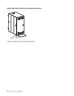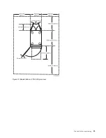
“Model 7014-T00 rack” on page 36
Hardware specifications provide detailed information for your rack, including dimensions, electrical,
power, temperature, environment, and service clearances.
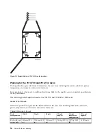
Planning for the 7953-94X and 7965-94Y rack
Rack specifications provide detailed information for your rack, including dimensions, electrical, power,
temperature, environment, and service clearances.
The following provide specifications for the 7953-94X and 7965-94Y rack.
Model 7953-94X and 7965-94Y rack:
Hardware specifications provide detailed information for your rack, including dimensions, electrical,
power, temperature, environment, and service clearances.
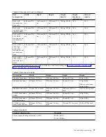
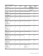
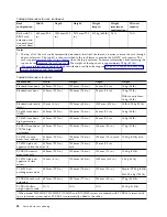
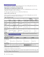
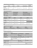
Table 71. Dimensions for rack
Width
Depth
Height
Weight (Empty)
Weight
(Maximum
configuration)
EIA unit
capacity
Rack only
600 mm (23.6
in.)
1039 mm
(40.9 in.)
2002 mm (78.8
in.)
130 kg (287 lb)
1140 kg (2512 lb) 42 EIA units
Rack with
standard
doors
600 mm (23.6
in.)
1095 mm
(43.1 in.)
2002 mm (78.8
in.)
138 kg (304 lb)
N/A
N/A
Rack with
triplex doors
600 mm (23.6
in.)
1206.2 -
1228.8 mm
(47.5 - 48.4
in.)
2002 mm (78.8
in.)
147 kg (324 lb)
N/A
N/A
Rack with
rear door
heat
exchanger
indicator
600 mm (23.6
in.)
1196 mm
(47.1 in.)
2002 mm (78.8
in.)
169 kg (373 lb)
N/A
N/A
Note:
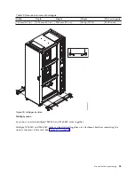
When the rack is delivered or is moved, outriggers are needed for stability. For more information about
outriggers, see “Side stabilizing outriggers” on page 52.
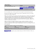
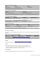
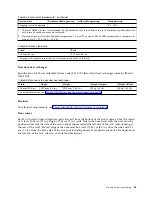
Table 72. Dimensions for doors
Door model
Width
Height
Depth
Weight
Standard front
door (FC EC01)
and
standard back
door (FC EC02)
597 mm (23.5 in.)
1925 mm (75.8 in.)
22.5 mm (0.9 in.)
7.7 kg (17 lb)
Triplex door (FC
EU21)
3
597.1 mm (23.5 in.) 1923.6 mm (75.7 in.)
105.7 mm (4.2 in.)
1
16.8 kg (37 lb)
128.3 mm (5.2 in.)
2
1
Measured from the front flat surface of the door.
2
Measured from the IBM logo on the front of the door.
3
Multiple racks that are placed side-by-side must have a 6 mm (0.24 in.) minimum clearance between racks to allow
the triplex front door to hinge properly. Feature code EC04 (Rack suite attachment kit) can be used to maintain the 6
mm (0.24 in.) minimum clearance between racks.
48
Site and hardware planning
Summary of Contents for 8408-44E
Page 1: ...Power Systems Site and hardware planning IBM...
Page 2: ......
Page 3: ...Power Systems Site and hardware planning IBM...
Page 16: ...xiv Site and hardware planning...
Page 18: ...2 Site and hardware planning...
Page 22: ...6 Site and hardware planning...
Page 51: ...Figure 19 Model 0555 and 7014 S25 plan view Site and hardware planning 35...
Page 192: ...176 Site and hardware planning...
Page 204: ...188 Site and hardware planning...
Page 205: ......
Page 206: ...IBM Printed in USA...

