
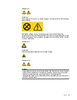
Statement
8:
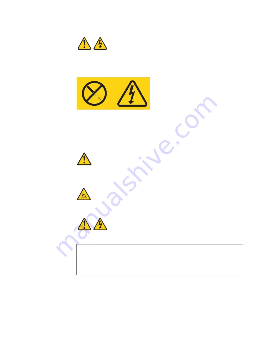
CAUTION:
Never
remove
the
cover
on
a
power
supply
or
any
part
that
has
the
following
label
attached.
Hazardous
voltage,
current,
and
energy
levels
are
present
inside
any
component
that
has
this
label
attached.
There
are
no
serviceable
parts
inside
these
components.
If
you
suspect
a
problem
with
one
of
these
parts,
contact
a
service
technician.
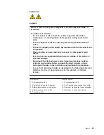
Statement
12:
CAUTION:
The
following
label
indicates
a
hot
surface
nearby.
Statement
13:
DANGER
Overloading
a
branch
circuit
is
potentially
a
fire
hazard
and
a
shock
hazard
under
certain
conditions.
To
avoid
these
hazards,
ensure
that
your
system
electrical
requirements
do
not
exceed
branch
circuit
protection
requirements.
Refer
to
the
information
that
is
provided
with
your
device
for
electrical
specifications.
Safety
xi
Summary of Contents for 8485E2U
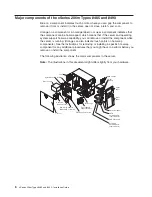
Page 3: ...xSeries 206m Types 8485 and 8490 Installation Guide...
Page 52: ...38 xSeries 206m Types 8485 and 8490 Installation Guide...
Page 62: ...48 xSeries 206m Types 8485 and 8490 Installation Guide...
Page 108: ...94 xSeries 206m Types 8485 and 8490 Installation Guide...
Page 109: ......
Page 110: ...Part Number 40K2367 Printed in USA 1P P N 40K2367...


