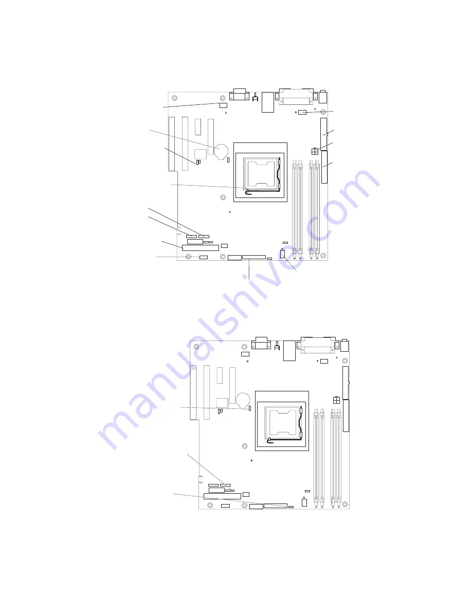
System-board
internal
connectors
The
following
illustration
shows
the
internal
connectors
on
the
system
board.
System fan 3
(rear fan)
Wake on LAN
SATA 2
SATA 0
Primary IDE
System fan 1
(fan sink)
Microprocessor
power
Main power
Diskette drive
(optional)
Front information panel
Battery
Microprocessor
Front USB
System fan 2
System-board
switches
and
jumpers
The
following
illustration
shows
the
switches
and
jumpers
on
the
system
board.
Force power on (JP8)
Clear CMOS (JP2)
Boot block (JP6)
System-board
external
connectors
The
following
illustration
shows
the
external
input/output
connectors
on
the
system
board.
14
xSeries
100
Type
8486:
User’s
Guide
Summary of Contents for 8486 - eServer xSeries 100
Page 1: ...xSeries 100 Type 8486 User s Guide ERserver...
Page 2: ......
Page 3: ...xSeries 100 Type 8486 User s Guide ERserver...
Page 24: ...12 xSeries 100 Type 8486 User s Guide...
Page 66: ...54 xSeries 100 Type 8486 User s Guide...
Page 67: ......
Page 68: ...Part Number 31R2069 Printed in USA 1P P N 31R2069...


