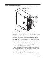
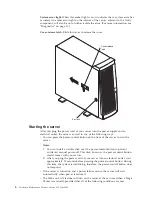


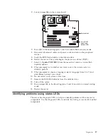

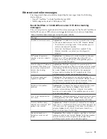


Front panel and system board LEDs
The server does not contain a diagnostic or information panel. The system error
LED is on the front panel inside the server. All of the remaining error LEDs are on
the system board, adjacent to the failing components. See “Diagnostic LEDs” for
information on identifying problems using these LEDs.
The meanings of these LEDs are as follows:
CPU1
Microprocessor number 1 (connector U12) fault
CPU2
Microprocessor number 2 (connector U11) fault
Fan 1
Fan number 1 (connector J10) failure (see note 1)
Fan 2
Fan number 2 (connector J18) failure (see note 1)
MEM1
DIMM number 1 (connector J19) fault
MEM 2
DIMM number 2 (connector J21) fault
MEM 3
DIMM number 3 (connector J23) fault
MEM 4
DIMM number 4 (connector J26) fault
VRM1
Microprocessor VRM number 1 (connector J42) fault (see note 1)
VRM2
Microprocessor VRM number 2 (connector J12) fault (see note 1)
Notes:
1.
The fan and VRM LEDs will illuminate only if the optional system
management adapter is installed in the server.
2.
The server does not support user-replaceable power supplies or fans.
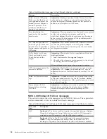
Diagnostic LEDs
You can use the diagnostic LEDs built into the server to quickly identify the type
of system error that occurred. The server is designed so that LEDs remain
illuminated when the server shuts down, as long as the power supply is operating
properly. This feature helps you to isolate the problem if an error causes the server
to shut down. To correct specific problems, see “Symptom-to-FRU index” on
page 105.
Table 2. Diagnostic LEDs
System Error LED (on the front
panel)
System board LED
Cause
On
A system error was detected. Check to
see which of the LEDs on the system
board are on.
None
The system error log is 75% or more
full or a Predictive Failure Analysis
(PFA) alert was logged.
On
MEM1, MEM2, MEM3, or MEM4
(system board)
A memory error occurred.
On
CPU1 or CPU2 (system board)
One of the microprocessors has
failed, or a microprocessor is
installed incorrectly.
On
Fan 1 or Fan 2
One of the fans has failed or is
operating too slowly.
On
VRM1 or VRM2 (system board)
One of the microprocessor VRMs has
failed, or a microprocessor VRM is
installed in the wrong connector.
18
Hardware Maintenance Manual: xSeries 220 Type 8645
Summary of Contents for 8645 - Eserver xSeries 220
Page 1: ...Hardware Maintenance Manual xSeries 220 Type 8645...
Page 2: ......
Page 3: ...Hardware Maintenance Manual xSeries 220 Type 8645...
Page 18: ...10 Hardware Maintenance Manual xSeries 220 Type 8645...
Page 36: ...28 Hardware Maintenance Manual xSeries 220 Type 8645...
Page 58: ...50 Hardware Maintenance Manual xSeries 220 Type 8645...
Page 102: ...94 Hardware Maintenance Manual xSeries 220 Type 8645...
Page 141: ...Related service information 133...
Page 142: ...134 Hardware Maintenance Manual xSeries 220 Type 8645...
Page 143: ...Related service information 135...
Page 144: ...136 Hardware Maintenance Manual xSeries 220 Type 8645...
Page 145: ...Related service information 137...
Page 146: ...138 Hardware Maintenance Manual xSeries 220 Type 8645...
Page 147: ...Related service information 139...
Page 148: ...140 Hardware Maintenance Manual xSeries 220 Type 8645...
Page 158: ...150 Hardware Maintenance Manual xSeries 220 Type 8645...
Page 159: ...Related service information 151...
Page 160: ...152 Hardware Maintenance Manual xSeries 220 Type 8645...
Page 167: ......


