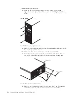
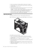
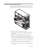
background image

7.

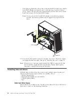
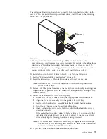
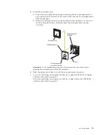
Carefully pull up on the end of the support bracket assembly that is closer to
the rear of the server; then, rotate and lift the support bracket assembly out of
the server.

8.

Store the support bracket assembly in a safe place.

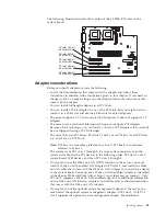
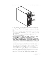
Working with adapters

You can install up to five peripheral component interconnect (PCI) adapters in the
PCI slots on the system board of the server. See the xSeries 220 ServerProven list at
http://www.ibm.com/pc/compat/ for a list of PCI adapters that the server
supports.

The server comes with an integrated video controller, which is a component on the
system board. When you install a video adapter, the server BIOS automatically
disables the integrated video controller.
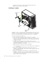
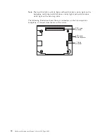
Note:

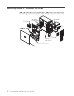
The illustrations in this document might differ slightly from your hardware.

60

Hardware Maintenance Manual: xSeries 220 Type 8645

Summary of Contents for 8645 - Eserver xSeries 220

Page 1: ...Hardware Maintenance Manual xSeries 220 Type 8645...

Page 2: ......

Page 3: ...Hardware Maintenance Manual xSeries 220 Type 8645...

Page 4: ...errors Changes are periodically made to the information herein these changes will be incorporated in new editions of the publication IBM may make improvements and or changes in the product s and or t...

Page 5: ...PC Server products Important safety information Be sure to read all caution and danger statements in this book before performing any of the instructions Leia todas as instru es de cuidado e perigo ant...

Page 6: ...pport Use the World Wide Web WWW to download Diagnostic BIOS Flash and Device Driver files File download address is http www us pc ibm com files html IBM online addresses The HMM manuals online addres...

Page 7: ...rogram 37 Choices available from the PXE boot agent menu 37 Tower to rack conversion 39 Installing options 51 Major components of the xSeries 220 server 52 System board 53 System board options connect...

Page 8: ...42X 4AX 51X 52X 5AX 119 System 120 Keyboards 121 Power cords 122 Related service information 123 Safety information 123 General safety 123 Electrical safety 124 Safety inspection guide 125 Handling e...

Page 9: ...t part of a shared DASD cluster A system might be part of a cluster if v The customer identifies the system as part of a cluster v One or more external storage units are attached to the system and at...

Page 10: ...if on see Front panel and system board LEDs on page 18 v Check the System Error Log If an error was recorded by the system see Symptom to FRU index on page 105 v Start the Diagnostic Programs See Dia...

Page 11: ...vironments that require superior microprocessor performance efficient memory management flexibility and large amounts of reliable data storage The IBM xSeries 220 server comes with a three year limite...

Page 12: ...installed v Three 3 5 in slim bays available in drive cage some models have a hard disk drive installed PCI expansion slots v Three 33 MHz 64 bit v Two 33 MHz 32 bit Power supply One 330 watt autosens...

Page 13: ...atts Electrical input v Sine wave input 50 60 Hz required v Input voltage low range Minimum 100 V ac Maximum 127 V ac v Input voltage high range Minimum 200 V ac Maximum 240 V ac v Input kilovolt ampe...

Page 14: ...lude a variety of application programs for the server Reliability availability and serviceability Three of the most important considerations in server design are reliability availability and serviceab...

Page 15: ...se a diskette from the drive Diskette drive activity light When this light is on it indicates that the diskette drive is in use SCSI activity light When this green light is flashing the controller is...

Page 16: ...f the server to start the server Notes 1 You can install a circular disk over the power control button to prevent accidental manual power off This disk known as the power control button shield comes w...

Page 17: ...device and the power switch on the power supply do not turn off the electrical current supplied to the device The device also might have more than one power cord To remove all electrical current from...

Page 18: ...10 Hardware Maintenance Manual xSeries 220 Type 8645...

Page 19: ...nd resolve hardware related problems v POST beep codes error messages and error logs The power on self test POST generates beep codes and messages to indicate successful test completion or the detecti...

Page 20: ...ne beep indicates that POST detected a problem For more information see Beep symptoms on page 105 POST error messages POST error messages occur during startup when POST finds a problem with the hardwa...

Page 21: ...rams are stored in upgradable read only memory ROM on the system board These programs are the primary method of testing the major components of the server Diagnostic error messages indicate that a pro...

Page 22: ...when you specify a diagnostic test for a device that is not present Aborted This result occurs when the test could not proceed because of the system configuration Warning This result occurs when a pos...

Page 23: ...the problem persists during normal server operations a software error might be the cause If you suspect a software problem refer to the information that comes with the software package Viewing the te...

Page 24: ...inimal configuration one at a time until the problem is isolated To use this method it is important to know the minimum configuration required for a system to power up see page 117 Recovering BIOS If...

Page 25: ...When prompted as to whether you want to save the current code to a diskette press N 9 When prompted to choose a language select a language from 0 to 7 and press Enter to accept your choice 10 Do not...

Page 26: ...server does not support user replaceable power supplies or fans Diagnostic LEDs You can use the diagnostic LEDs built into the server to quickly identify the type of system error that occurred The ser...

Page 27: ...recommended by the manufacturer If your system has a module containing a lithium battery replace it only with the same module type made by the same manufacturer The battery contains lithium and can ex...

Page 28: ...nd system reliability For a typical IBM xSeries server you should make sure v Each of the drive bays has either a drive or a filler panel installed v The cover is in place during normal operation v Th...

Page 29: ...nnect two workstations without a hub or if you are not using a hub with X ports use a crossover cable Note To determine whether a hub has an X port check the port label If the label contains an X the...

Page 30: ...ad parameters If necessary remove any LED parameter settings when you load the device drivers Data is incorrect or sporadic Check the following v Make sure that you are using Category 5 cabling when o...

Page 31: ...fter loading AFT NLM but before any bind command can be issued Action Load the driver for the supported adapter and try loading the AFT module again If the problem persists contact your network suppli...

Page 32: ...perly in the slot and try loading the AFT module again If the problem persists contact your network supplier AFT is not supported on this version of NetWare Explanation The NetWare on your server is n...

Page 33: ...ot allocate enough memory for other structures Action 1 From the Windows NT desktop select Start Control Panel Networks Adapters 2 Select your IBM Ethernet adapter from the list 3 Select Properties Ad...

Page 34: ...nal Explanation Team nn Virtual adapter or Team is initialized Action None 09 Informational Explanation Team nn Primary adapter is switching over Action None 10 Warning Explanation Team nn Adapter lin...

Page 35: ...rred primary adapter took over Action None 20 Informational Explanation Team nn Preferred secondary adapter took over Action None 21 Warning Explanation Team nn Primary adapter does not sense any Prob...

Page 36: ...28 Hardware Maintenance Manual xSeries 220 Type 8645...

Page 37: ...Utility program is part of the BIOS code that comes with your server You can use this program to change network startup boot protocols and startup boot order to select operating system wake up suppor...

Page 38: ...store Settings Load Default Settings Exit Setup Configuration Setup Utility Notes 1 You can press F1 to display help information for a selected menu item 2 The choices on some menus might differ sligh...

Page 39: ...ator password is set and then forgotten it cannot be overridden or removed You must replace the system board The administrator password provides access to all choices on the Configuration Setup Utilit...

Page 40: ...oice to modify settings that control features of the core chip set on the system board Attention Do not make changes in this option unless directed to do so by an IBM authorized service representative...

Page 41: ...stomized settings v Restore Settings Select this choice to discard the changes and retain the current settings v Load Default Settings Select this choice to discard the changes and restore the factory...

Page 42: ...n switch block 1 on the system board to the opposite side of the switch This bypasses the power on password 4 Install the server cover see Installing the cover on page 79 and connect all external cabl...

Page 43: ...lity main menu This limited access might include changing or deleting the power on password Using the SCSISelect utility program SCSISelect is a built in menu driven configuration utility program that...

Page 44: ...an make updates you must know the ID of the device whose parameters you want to configure Note The Maximum Sync Transfer Rate is the transfer rate for Ultra SCSI devices The transfer rate for Ultra 16...

Page 45: ...o press Ctrl S 3 Use the arrow keys or press Enter to select a choice from the menu v Press Esc to return to the previous menu v Press the F4 key to exit 4 Follow the instructions on the screen to cha...

Page 46: ...during initialization for a Ctrl S input 2 seconds default 3 seconds 5 seconds 8 seconds v Legacy OS wake up support Select this choice to allow disallow a non windows operating system to use adapter...

Page 47: ...or tapes 2 Turn off the system and any attached devices 3 Disconnect all power cords from the system and electrical outlets 4 Note the location of any remaining cables then disconnect all other cables...

Page 48: ...system board then disconnect the fan cable from the system board Note Refer to the system service label for system board connector locations b Grasp the rear of the support bracket assembly and rotate...

Page 49: ...front of the support bracket assembly away from the system and set the assembly aside for later installation Support bracket assembly Figure 2 Removing the support bracket assembly Tower to rack conv...

Page 50: ...then lift the front door and bezel assembly out of the tab openings on the bottom of the system and store the assembly for possible future use 8 Carefully turn the system open side up on a flat surfa...

Page 51: ...ation location a If the system has hot swap drives installed note their locations then remove them see Installing a hot swap hard disk drive in bay 5 6 or 7 on page 69 and place them in a safe place b...

Page 52: ...gh the opening in the new location on the system then connect the cable to the system board where you disconnected it earlier Note If your cable has two connectors make sure that you connect both of t...

Page 53: ...use a flat blade screwdriver to push in the tabs inside the plastic cover on the top of the system then remove the plastic cover and store it for possible future use b Grasp the metal handle and slid...

Page 54: ...at comes with the conversion kit a Carefully turn the system so that the cover release latch side is down on a flat surface then align the bottom cover with the frame of the system b Slide the cover t...

Page 55: ...ller panel 15 If your system does not have USB support install the USB bezel insert over the empty USB block on the front of your system a Align the top of the USB bezel insert with the top of the USB...

Page 56: ...bracket assemblies on the system a Align the bracket marked with an L with the holes on the left side of the system then use two M3 5 screws to attach the bracket to the system b Repeat this step to...

Page 57: ...18 Attach the four rack support wheels to the sides of the system Rack support wheels Rack support wheels Figure 16 Attaching the rack support wheels Tower to rack conversion 49...

Page 58: ...50 Hardware Maintenance Manual xSeries 220 Type 8645...

Page 59: ...oving a microprocessor 78 Installing the bezel 79 Installing the cover 79 Connecting external options 80 I O connector locations 81 Input Output ports 81 Parallel port 82 Viewing or changing the port...

Page 60: ...m your hardware The following illustration shows the locations of major components in the server Rear adapter retaining bracket Front adapter support bracket Drive cage Microprocessor Memory modules C...

Page 61: ...oltage regulator module VRM 1 J42 DIMM 1 J23 DIMM 2 J21 DIMM 3 J19 DIMM 4 J18 PCI 1 J29 PCI 2 J31 PCI 3 J35 PCI 4 J39 PCI 5 J40 Battery BH1 System management J32 System board internal cable connectors...

Page 62: ...if the optional system management adapter is installed in the server the system management connector J32 is dedicated for use by the system management adapter 2 The system management adapter is also k...

Page 63: ...d switches on the system board Flash ROM page swap jumper J38 Switch block System board jumper blocks Any jumper blocks on the system board that are not shown in the illustration are reserved For norm...

Page 64: ...r the server monitor and any other options that you intend to install v Back up all important data before you make changes to disk drives v Have a small flat blade screwdriver available v For a list o...

Page 65: ...er on its side so that the system board is facing you If you do so rotate the feet in towards the server so that they do not break off due to the weight of the server Removing the side cover The follo...

Page 66: ...side to install or remove components Removing the bezel The following illustration shows how to remove the bezel from the server Note The illustrations in this document might differ slightly from your...

Page 67: ...cords 3 Remove the side cover see Removing the side cover on page 57 4 If the server is a non hot swap model continue with step 7 on page 60 5 If the server is a hot swap model press down on the latc...

Page 68: ...adapters in the PCI slots on the system board of the server See the xSeries 220 ServerProven list at http www ibm com pc compat for a list of PCI adapters that the server supports The server comes wit...

Page 69: ...g of PCI interrupts v The server has two PCI buses PCI slots 1 and 2 are on PCI bus A and PCI slots 3 4 and 5 are on PCI bus B Note PCI bus A is sometimes referred to as bus 0 PCI bus B is sometimes r...

Page 70: ...cover See Removing the side cover on page 57 for details 3 Carefully remove the support bracket assembly from the server see Removing the support bracket assembly on page 59 Store the cover and the s...

Page 71: ...board b Press the adapter firmly into the expansion slot Attention When you install an adapter in the server be sure that it is completely and correctly seated in the system board connector before you...

Page 72: ...the support bracket assembly then go to Installing the cover on page 79 Note If the server is a hot swap model reinstall the VRM in connector J42 after you reinstall the support bracket assembly See...

Page 73: ...1 44 MB v The xSeries 220 server supports two 5 25 inch drives and four SCSI hard disk drives The server does not support IDE hard disk drives Some models support hot swap hard disk drives Other mode...

Page 74: ...ling electrostatic discharge sensitive devices on page 126 and the documentation that comes with the drive 2 Choose the bay in which you want to install the drive 3 Check the instructions that come wi...

Page 75: ...the drive from the bag and place it on a static protective surface 7 Set any jumpers or switches on the drive according to the documentation that comes with the drive 8 Push the drive into the bay 9...

Page 76: ...that contains the drive rails and screws from inside the drive cage 6 Install rails on each drive in the drive cage a Pull the blue slide rails out of the plastic bag b Install the screws on the sides...

Page 77: ...accessing the hard disk drive When this occurs the SCSI activity light on the front of the server also illuminates The SCSI activity light is illustrated and described in Server controls and indicato...

Page 78: ...activity light and hard disk drive status light on the hot swap drive The following illustration shows the rear connectors on the hot swap drive backplane as viewed from the rear of the server SCSI ca...

Page 79: ...disk drives in these bays 3 Remove the filler panel from one of the empty hot swap bays by inserting your finger into the depression at the left side of the filler panel and pulling it away from the...

Page 80: ...memory See the ServerProven list at http www ibm com pc compat for a list of memory modules for use with the server 3 Installing or removing DIMMs changes the configuration information in the server...

Page 81: ...on page 79 Attention When you restart the server the system displays a message indicating that the memory configuration has changed v If you installed additional memory start the Configuration Setup...

Page 82: ...ou install a new or additional microprocessor use microprocessors that have the same cache size and type and the same clock speed Microprocessor internal clock frequencies and external clock frequenci...

Page 83: ...e connector Microprocessor 2 Terminator card Microprocessor 2 connector Microprocessor orientation indicator Lever Attention To avoid bending the pins do not use excessive force when pressing the micr...

Page 84: ...iner Heat sink a Peel the plastic protective strip off the bottom of the heat sink Make sure that the square of thermal material is still on the bottom of the heat sink b Align and place the heat sink...

Page 85: ...blade screwdriver into the tab on the fan sink retainer e Press down and in with the screwdriver handle to snap the fan sink retainer into place in the slot on the microprocessor over the fan sink f C...

Page 86: ...le electrostatic discharge ESD sensitive devices take precautions to avoid damage from static electricity For details on handling these devices see Handling electrostatic discharge sensitive devices o...

Page 87: ...g a microprocessor on page 74 9 If you are not replacing the microprocessor a Reinstall the terminator card in the empty microprocessor connector b Press the release lever down to lock the terminator...

Page 88: ...to the slots 3 Close the cover release latch to pull the cover forward and lock the cover in place 4 Make sure that the stabilizing feet are rotated outward so that they properly support the server 5...

Page 89: ...l B Ethernet Video Input Output ports This section provides information about the input output I O ports on the server These ports include the following v One parallel port v One video port v One keyb...

Page 90: ...supports the ECP and EPP modes To view or change the parallel port assignment do the following 1 Restart the server and watch the monitor screen 2 When the message Press F1 for Configuration Setup ap...

Page 91: ...I PE paper end PE paper end 13 I SLCT select SLCT select 14 O AUTO FD feed AUTO FD 15 I ERROR ERROR 16 O INIT INIT 17 O SLCT IN SLCT IN 18 Ground Ground 19 Ground Ground 20 Ground Ground 21 Ground Gro...

Page 92: ...rver has two Universal Serial Bus USB ports which configure automatically USB is a serial interface standard for telephony and multimedia devices It uses Plug and Play technology to determine the type...

Page 93: ...system board Note If you attach a standard non USB keyboard to the keyboard connector the USB ports and devices will be disabled during the power on self test POST The following table shows the pin nu...

Page 94: ...able but you can disable it by installing a PCI video adapter Note If you install a PCI video adapter the server BIOS will automatically disable the integrated video controller The following table sho...

Page 95: ...connect internal SCSI devices to the SCSI controller on the system board A SCSI cable comes with the models that have the hot swap drive cage option If you plan to attach external SCSI devices you mu...

Page 96: ...ta P 48 Data P 15 Ground 49 Ground 16 DIFFSENS 50 Ground 17 Term power 51 Term power 18 Term power 52 Term power 19 Reserved 53 Reserved 20 Ground 54 Ground 21 Attention 55 Attention 22 Ground 56 Grou...

Page 97: ...The device drivers are provided on the ServerGuide CDs Failover for redundant Ethernet The IBM 10 100 Ethernet Adapter or the IBM 10 100 Etherjet PCI family of adapters are optional redundant network...

Page 98: ...re tagged with 4 additional bytes which increase the packet size and indicate a priority level When you send these packets out on the network the higher priority packets are transferred first Priority...

Page 99: ...ups This can simplify network administration when you are connecting clients to servers that are geographically dispersed across a building campus or enterprise network Normally VLANs are configured a...

Page 100: ...me is for information only and does not need to match the name on the switch 6 Click Join VLAN Repeat steps 3 on page 91 through 5 for each VLAN that you want the server to join The VLANs that you add...

Page 101: ...N function in the server you must install a Wake on LAN enabled Ethernet NIC adapter in PCI slot 1 and use the Ethernet cable that comes with the Ethernet adapter to connect the Ethernet adapter to th...

Page 102: ...94 Hardware Maintenance Manual xSeries 220 Type 8645...

Page 103: ...page 123 v Review the information in System reliability considerations on page 56 To remove the button kit do the following 1 Power off the server if it is on 2 Unplug the server 3 Remove the cover se...

Page 104: ...e 58 4 Remove the cover see Removing the side cover on page 57 5 Remove the support bracket see Removing the support bracket assembly on page 59 6 Remove any hard disk drives or drive fillers from the...

Page 105: ...e cover on page 57 5 Remove the support bracket see Removing the support bracket assembly on page 59 6 Remove any hard disk drives or drive fillers from the drives 7 Disconnect the hard disk drive cab...

Page 106: ...ables from the planar and drives 5 Remove the screws from the rear of the server 6 Gently move the power supply away from the chassis and lift it out of the server Rear fan Before you begin v Read Saf...

Page 107: ...edle nosed pliers to pull the extensions through the apertures 11 Reconnect cables System board Before you begin v Read Safety information on page 123 v Review the information in System reliability co...

Page 108: ...ore you begin v Read Safety information on page 123 v Review the information in System reliability considerations on page 56 To remove the CD ROM drive do the following 1 Power off the server if it is...

Page 109: ...cage 6 Gently slide the floppy disk drive toward the rear of the server and lift it out Bezel release latch Before you begin v Read Safety information on page 123 v Review the information in System re...

Page 110: ...nformation in System reliability considerations on page 56 To remove the top side cover do the following 1 Power off the server if it is on 2 Unplug the server 3 Remove the cover see Removing the side...

Page 111: ...or side wall of the handle 4 Lift up on the handle cap to separate it from the handle support To remove the handle support do the following 1 Power off the server if it is on 2 Unplug the server 3 Fir...

Page 112: ...the side cover see Removing the side cover on page 57 4 Remove all adapter cards see Installing an adapter on page 62 5 Rotate the adapter retainer to the open position 6 Grasp the adapter retainer an...

Page 113: ...n page 1 The Symptom to FRU lists symptoms errors and the possible causes The most likely cause is listed first Use this Symptom to FRU index to help you decide which FRUs to have available when servi...

Page 114: ...sk register failed 1 System Board 2 2 1 Interrupt vector loading failed 1 System Board 2 2 2 Keyboard controller failed 1 System Board 2 Keyboard 2 2 3 CMOS power failure and checksum checks failed 1...

Page 115: ...ry after reseating I2C cables between a system management adapter PCI slot 2 J31 and planar J32 b DASD I2C on planar J43 and DASD backplane 3 System Board 4 DIMMs 5 Power Supply 6 I2C Cable 3 3 3 No o...

Page 116: ...ge 117 Diagnostic error codes Note In the following error codes if XXX is 000 195 or 197do not replace a FRU The description for these error codes are 000 The test passed 195 The Esc key was pressed t...

Page 117: ...ion 035 XXX S99 Failed RAID test on PCI slot S S number of failing PCI slot Check System Error Log before replacing a FRU 1 Adapter 2 SCSI Backplane 3 Cable 035 XXX SNN Check System Error Log before r...

Page 118: ...ay 1 Fixed Disk 3 264 XXX 0NN NN SCSI ID of failing Tape Drive 1 Tape Cartridge if user executed the Read Write Tape Drive test XXX 256 2 SCSI or power cable connected to the tape drive with SCSI ID N...

Page 119: ...skette drive or the diskette drive does not work 1 If there is a diskette in the drive verify that a The diskette drive is enabled in the Configuration Setup utility program b The diskette is good and...

Page 120: ...f the startup boot sequence settings have been altered be sure the CD ROM is first in the boot sequence v If more than one CD ROM drive is installed be sure that only one drive is set as the primary d...

Page 121: ...or Note Be sure to load the default settings and any additional desired settings then save the configura tion 1 Run Configuration Setup 2 Battery 3 Failing Device 4 System Board 163 Real Time Clock er...

Page 122: ...1 Keyboard or keyboard controller error 1 Keyboard 2 System Board 303 Keyboard controller error 1 System Board 2 Keyboard 602 Invalid diskette boot record 1 Diskette 2 Diskette Drive 3 Cable 4 System...

Page 123: ...nfiguration Setup 2 CD ROM Drive 3 CD ROM Power Cable 4 IDE Cable 5 System Board 6 Battery 8603 Pointing Device Error 1 Pointing Device 2 System Board 00012000 Processor machine check 1 Update BIOS 2...

Page 124: ...rocessors are the same stepping level and cache size 2 Microprocessor 1 01298002 No update data for microprocessor 2 1 Ensure all microprocessors are the same stepping level and cache size 2 Microproc...

Page 125: ...ot identify the failure the Devices List is incorrect or the system is inoperative Note A corrupt CMOS can cause undetermined problems If power problems are suspected 1 Power off the computer 2 Be sur...

Page 126: ...replacing that adapter does not correct the problem suspect the system board then the power supply 2 If you suspect a networking problem and all the system tests pass suspect a network cabling proble...

Page 127: ...X 31X 32X 3AX 41X 42X 4AX 51X 52X 5AX This parts listing supports the following models 21X 22X 2AX 31X 32X 3AX 41X 42X 4AX 51X 52X 5AX 2 3 4 5 6 7 8 9 10 11 12 13 14 15 16 17 18 19 20 21 22 23 24 25 1...

Page 128: ...752 22 Memory 128MB RDIMM All models 33L3143 22 Memory 256MB RDIMM optional All models 33L3145 22 Memory 512MB RDIMM optional All models 33L3151 22 Memory 1GB RDIMM optional All models 33L3153 23 Plan...

Page 129: ...ls 00N7070 Slide assembly optional All models 00N7072 Left EIA flange optional All models 00N7190 Right EIA flange optional All models 00N7192 Misc parts optional All models 00N7193 Rigid arm optional...

Page 130: ...fghanistan Algeria Andorra Angola Austria Belgium Benin Bulgaria Burkina Faso Burundi Cameroon Central African Rep Chad Czech Republic Egypt Finland France French Guiana Germany Greece Guinea Hungary...

Page 131: ...hazards to the customer or that makes the equipment unsafe v Before you start the machine ensure that other service representatives and the customer s personnel are not in a hazardous position v Place...

Page 132: ...hanical inspection Working near power supplies Removing or installing main units v Before you start to work on the machine unplug the power cord If you cannot unplug it ask the customer to power off t...

Page 133: ...ntent of this inspection guide is to assist you in identifying potentially unsafe conditions on these products Each machine as it was designed and built had required safety items installed to protect...

Page 134: ...the same charge Notes 1 Use product specific ESD procedures when they exceed the requirements noted here 2 Make sure that the ESD protective devices you use have been certified ISO 9000 as fully effe...

Page 135: ...n statement appear in this section under statement 1 Be sure to read all caution and danger statements before performing any of the instructions v Statement 1 DANGER Electrical current from power tele...

Page 136: ...ode if not properly used handled or disposed of Do not v Throw or immerse into water v Heat to more than 100 C 212 F v Repair or disassemble Dispose of the battery as required by local ordinances or r...

Page 137: ...pply do not turn off the electrical current supplied to the device The device also might have more than one power cord To remove all electrical current from the device ensure that all power cords are...

Page 138: ...s v Conecte todos os equipamentos ao qual esse produto ser conectado a tomadas corretamente instaladas v Sempre que poss vel utilize apenas uma das m os para conectar ou desconectar cabos de sinal v N...

Page 139: ...reio para a IBM Instru o 3 PRECAUCI N Quando produtos a laser unidades de CD ROM unidades de DVD dispositivos de fibra tica transmissores etc estiverem instalados observe o seguinte v N o remova as ta...

Page 140: ...ositivo O dispositivo tamb m pode ter mais de um cabo de alimenta o Para remover toda a corrente el trica do dispositivo assegure que todos os cabos de alimenta o estejam desconectados da fonte de ene...

Page 141: ...Related service information 133...

Page 142: ...134 Hardware Maintenance Manual xSeries 220 Type 8645...

Page 143: ...Related service information 135...

Page 144: ...136 Hardware Maintenance Manual xSeries 220 Type 8645...

Page 145: ...Related service information 137...

Page 146: ...138 Hardware Maintenance Manual xSeries 220 Type 8645...

Page 147: ...Related service information 139...

Page 148: ...140 Hardware Maintenance Manual xSeries 220 Type 8645...

Page 149: ...c bl s tout quipement connect ce produit v Lorsque cela est possible n utilisez qu une seule main pour connecter ou d connecter les c bles d interface v Ne mettez jamais un quipement sous tension en...

Page 150: ...uits laser sont install s tels que des unit s de CD ROM ou de DVD des p riph riques contenant des fibres optiques ou des metteurs r cepteurs prenez connaissance des informations suivantes v N ouvrez p...

Page 151: ...coupent pas l arriv e de courant lectrique l int rieur de la machine Il se peut que votre unit dispose de plusieurs cordons d alimentation Pour isoler totalement l unit du r seau lectrique d branchez...

Page 152: ...osen mit ordnungsgem geerdetem Schutzkontakt anschlie en v Signalkabel m glichst einh ndig anschlie en oder l sen v Keine Ger te einschalten wenn die Gefahr einer Besch digung durch Feuer Wasser oder...

Page 153: ...e Einheiten mit Glasfaserkabeln oder Transmitter installiert ist beachten Sie folgendes v Das Entfernen der Abdeckungen des CD ROM Laufwerks kann zu gef hrlicher Laserstrahlung f hren Es befinden sich...

Page 154: ...er am Netzteil wird die Stromversorgung f r den Server nicht unterbrochen Der Server k nnte auch mehr als ein Netzkabel aufweisen Um die gesamte Stromversorgung des Servers auszuschalten mu sichergest...

Page 155: ...are qualsiasi apparecchiatura collegata a questo prodotto ad una presa elettrica correttamente cablata e munita di terra di sicurezza v Quando possibile collegare o scollegare i cavi di segnale con un...

Page 156: ...ionali e locali Avviso 3 ATTENZIONE Quando si installano prodotti laser come ad esempio le unit DVD CD ROM a fibre ottiche o trasmettitori prestare attenzione a quanto segue v Non rimuovere i coperchi...

Page 157: ...o sull alimentatore non disattiva la corrente elettrica fornita all unit L unit potrebbe disporre di pi di un cavo di alimentazione Per disattivare la corrente elettrica dall unit accertarsi che tutti...

Page 158: ...150 Hardware Maintenance Manual xSeries 220 Type 8645...

Page 159: ...Related service information 151...

Page 160: ...152 Hardware Maintenance Manual xSeries 220 Type 8645...

Page 161: ...tomas de alimentaci n con un cableado correcto cualquier equipo que vaya a estar conectado a este producto v Si es posible utilice una sola mano cuando conecte o desconecte los cables de sent al v No...

Page 162: ...legislaci n local Declaraci n 3 PRECAUCI N Cuando instale productos l ser como por ejemplo CD ROM unidades DVD dispositivos de fibra ptica o transmisores tenga en cuenta las advertencias siguientes v...

Page 163: ...imentaci n no apagan la corriente el ctrica suministrada al dispositivo Es posible tambi n que el dispositivo tenga m s de un cable de alimentaci n Para eliminar la corriente el ctrica del dispositivo...

Page 164: ..._____________________ _________________________________________ 2 What would you like to see added changed or deleted in this manual _________________________________________ _________________________...

Page 165: ...Have the same adapters attachments in the same locations 4 Have the same address jumpers terminators cabling 5 Have the same software versions and levels 6 Have the same Reference Diagnostics Diskette...

Page 166: ...s for particular purpose These products are offered and warranted solely by third parties Trademarks The following items are trademarks of the IBM Corporation in the United States or other countries o...

Page 167: ......

Page 168: ...Part Number 06P1822 File Number Printed in the United States of America on recycled paper containing 10 recovered post consumer fiber 1P P N 06P1822...

Reviews: