

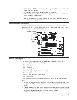


SCSI port
The server has an integrated small computer system interface (SCSI) controller
with an internal connector (J41) on the system board. This controller supports an
Ultra160 SCSI internal channel. This channel supports up to 15 SCSI devices. In
addition, this controller uses:
v
Double-transition clocking to achieve high transfer rates
v
Domain name validation to negotiate compatible data transfer speeds with each
device
v
Cyclic-redundancy checking (CRC), instead of the usual parity checking, to
significantly improve data reliability
v
An active terminator on the system board for SCSI bus termination
If you install a SCSI adapter in the server, you can use its SCSI connector to
connect different types of small computer system interface (SCSI) devices.
Note:
If you install a PCI redundant array of independent disks (RAID) adapter,
you can move the SCSI cable from the system-board SCSI connector to an
internal channel connector on the RAID adapter if you want to control the
internal drives from the adapter.
SCSI cabling requirements
A SCSI cable comes with the server so that you can connect internal SCSI devices
to the SCSI controller on the system board. A SCSI cable comes with the models
that have the hot-swap drive cage option. If you plan to attach external SCSI
devices, you must install an optional SCSI adapter and order additional SCSI
cables.
For information about the maximum length of SCSI cable between the terminated
ends of the cable, refer to the ANSI SCSI standards. Adhering to these standards
will help ensure that the server operates properly.
Setting SCSI IDs
Each SCSI device that is connected to a SCSI controller or adapter must have a
unique SCSI ID. This ID enables the SCSI controller or adapter to identify the
device and ensure that different devices on the same SCSI channel do not attempt
to transfer data simultaneously. SCSI devices that are connected to different SCSI
channels can have duplicate SCSI IDs.
To install external SCSI devices, you must first install an optional SCSI PCI
adapter. Refer to the information that is provided with the device for instructions
to set its SCSI ID.
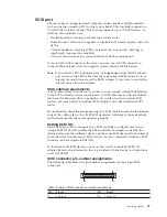
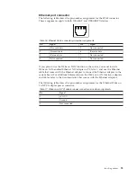
SCSI connector pin-number assignments
The following table shows the pin-number assignments for the 68-pin SCSI
connectors.
34
1
68
35
Table 15. 68-pin SCSI connector pin-number assignments
Pin
Signal
Pin
Signal
1
+Data 12
35
-Data 12
Installing options
87
Summary of Contents for 8645 - Eserver xSeries 220
Page 1: ...Hardware Maintenance Manual xSeries 220 Type 8645...
Page 2: ......
Page 3: ...Hardware Maintenance Manual xSeries 220 Type 8645...
Page 18: ...10 Hardware Maintenance Manual xSeries 220 Type 8645...
Page 36: ...28 Hardware Maintenance Manual xSeries 220 Type 8645...
Page 58: ...50 Hardware Maintenance Manual xSeries 220 Type 8645...
Page 102: ...94 Hardware Maintenance Manual xSeries 220 Type 8645...
Page 141: ...Related service information 133...
Page 142: ...134 Hardware Maintenance Manual xSeries 220 Type 8645...
Page 143: ...Related service information 135...
Page 144: ...136 Hardware Maintenance Manual xSeries 220 Type 8645...
Page 145: ...Related service information 137...
Page 146: ...138 Hardware Maintenance Manual xSeries 220 Type 8645...
Page 147: ...Related service information 139...
Page 148: ...140 Hardware Maintenance Manual xSeries 220 Type 8645...
Page 158: ...150 Hardware Maintenance Manual xSeries 220 Type 8645...
Page 159: ...Related service information 151...
Page 160: ...152 Hardware Maintenance Manual xSeries 220 Type 8645...
Page 167: ......


