

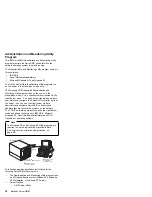


Installing the Server Utility Programs
Note
If you are installing the OS/2, Novell
NetWare/Intranetware, or SCO OpenServer versions
of the server utility programs, you must use diskettes.
Go to
You can install the server utility programs in one of two
ways:
Using ServerGuide (see “Installing the Server Utility
Programs using ServerGuide”)
Using diskettes (see “Installing the Server Utility
Programs using Diskettes”)
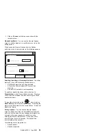
Installing the Server Utility Programs using
ServerGuide:
You can install the server utility programs
using the CoPilot feature of ServerGuide. Refer to the
ServerGuide package for more information.
Once you have installed the server utility programs, go to
“Using the Server Utility Programs” on page 23 for
information on how to use them.
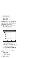
Installing the Server Utility Programs using
Diskettes:
This section contains installation instructions
and information about using the IBM OS/2 server utility,
Microsoft Windows NT server utility, Novell
NetWare/IntraNetware server utility, and SCO OpenServer
utility.
Note
You must first make the ServeRAID diskettes using
the Diskette Factory feature of ServerGuide. Refer to
the ServerGuide package for instructions.
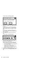
IBM OS/2 Server Utility Programs:
To install the
IBM OS/2 server utility program using diskettes:
1. Insert the
IBM ServeRAID Device Driver Diskette into
the diskette drive.
2. Create an IPSRAID directory on the hard disk. Type:
md d:\ipsraid
(where
d: is the hard disk drive letter)
3. Copy the following file to the target directory. Type:
copy a:\remote\servers\os2\ipsadm.exe d:\ipsraid
(where
a: is the diskette drive letter and d: is the hard
disk drive letter)
4. Copy the icon file to the target directory. Type:
copy a:\remote\servers\os2\ipsadm.ico
d:\ipsraid\ipsadm.ico
20
Netfinity Server HMM
Summary of Contents for 86604RU - Netfinity 5500 - 4RU
Page 2: ......
Page 8: ...vi Netfinity Server HMM...
Page 214: ...1 Hard disk drive 2 Drive tray handle open position 206 Netfinity Server HMM...
Page 244: ...Screws 236 Netfinity Server HMM...
Page 247: ...Netfinity 5500 Type 8660 239...
Page 314: ...306 Netfinity Server HMM...
Page 324: ...316 Netfinity Server HMM...
Page 325: ...Related service information 317...
Page 326: ...318 Netfinity Server HMM...
Page 327: ...Related service information 319...
Page 340: ...332 Netfinity Server HMM...
Page 341: ...Related service information 333...
Page 346: ...338 Netfinity Server HMM...
Page 402: ...IBM Part Number 00N5902 Printed in U S A S1 L 98 3...


