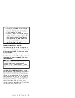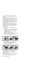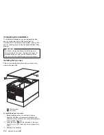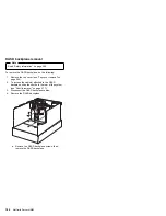
4. Tighten the two thumbscrews
.1/
on the back edge of
the cover.
5. If you disconnected any cables from the back of the
server, reconnect the cables; then, plug the power
cords into properly grounded electrical outlets.
Notes
1. If you are in the United Kingdom and have a
modem or fax machine attached to the
server, reconnect the telephone line
after
you plug in the power cords.
2. If necessary, see “Input/output connectors
and expansion slots” on page 209 for
connector locations.
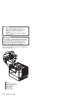
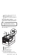
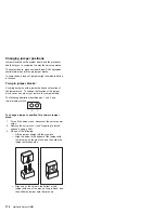
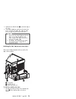
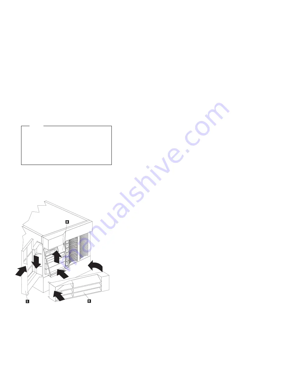
Installing the trim bezels and server door:
Refer to the following illustration while you perform the
steps in this procedure.
.1/
Server door
.2/
NetBAY3 bezel
.3/
Media-bay trim bezel
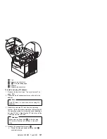
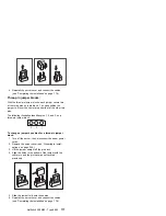
To install the media-bay trim bezel:
1. Insert the two tabs on the top of the media-bay trim
bezel
.3/
in the matching holes on the server
chassis.
Netfinity 5500 M20 - Type 8662
179
Summary of Contents for 866251Y - Netfinity 5500 M20
Page 2: ......
Page 8: ...vi Netfinity Server HMM...
Page 336: ...32 33 33 34 35 36 37 38 39 40 41 42 43 328 Netfinity Server HMM...
Page 346: ...338 Netfinity Server HMM...
Page 354: ...346 Netfinity Server HMM...
Page 355: ...Related service information 347...
Page 356: ...348 Netfinity Server HMM...
Page 357: ...Related service information 349...
Page 368: ...360 Netfinity Server HMM...
Page 369: ...Related service information 361...
Page 385: ......
Page 386: ...IBM Part Number 09N1015 Printed in U S A S37L 2 2 1...

