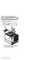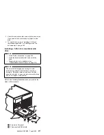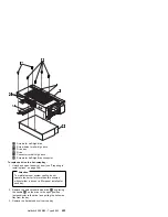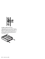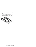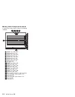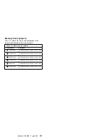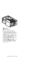
7. Place the drive so that the slide rails engage in the
bay guide rails. Push the drive into the bay and
attach it with the two screws
.1/
from the filler panel.
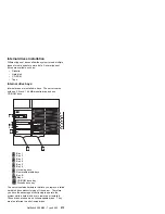
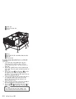
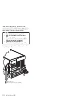
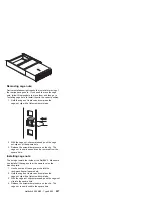
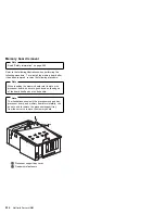
8. Loosen the four thumbscrews
.8/
on the shuttle at
the back of the server.
9. Pull the shuttle
.7/
toward the back of the server.
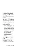
10. Connect one of the connectors on the SCSI cable for
the removable-media drive bays
.6/
to the back of
the drive
.5/
.
11. Connect a power cable to the back of the drive.
Power cables for removable-media drives come
installed in the server. The connectors are keyed and
can be inserted only one way.
12. If you have not previously done so, connect the SCSI
cable to either the RAID channel 1 connector on the
system board or to an additional SCSI adapter that
you have installed. For more information see “SCSI
IDs” on page 215.
If you choose to use the RAID channel 1 connector to
attach the removable-media drive:
a. Remove the processor support tray to allow
access to the RAID channel 1 connector. (See
“Processor support tray removal” on page 259.)
b. Disconnect the cable from the RAID channel 1
connector on the system board. (See “System
board component locations” on page 279 for the
location of the RAID channel 1 connector.) You
can leave the other end of the cable connected
to the external SCSI connector on the back of
the server, but you will not be able to use the
external SCSI connector to attach external SCSI
devices without adding an additional SCSI
adapter.
c. Connect the SCSI cable from the
removable-media drive to the RAID channel 1
connector on the system board.
d. Install the processor support tray. (See
“Processor support tray installation” on
page 261.)
13. If you are installing another 5.25-inch drive, do so at
this time. Otherwise, continue with the next step.
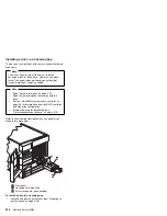
14. Push the shuttle
.7/
toward the front of the server
and tighten the four thumbscrews
.8/
at the back of
the shuttle.
15. Install the media-bay trim bezel and the NetBAY3
bezel that you removed earlier. (See “Installing the
trim bezels and server door” on page 179.)
16. If you have other options to install or remove, do so
now; otherwise, go to “Completing the installation” on
page 178.
Netfinity 5500 M20 - Type 8662
219
Summary of Contents for 866251Y - Netfinity 5500 M20
Page 2: ......
Page 8: ...vi Netfinity Server HMM...
Page 336: ...32 33 33 34 35 36 37 38 39 40 41 42 43 328 Netfinity Server HMM...
Page 346: ...338 Netfinity Server HMM...
Page 354: ...346 Netfinity Server HMM...
Page 355: ...Related service information 347...
Page 356: ...348 Netfinity Server HMM...
Page 357: ...Related service information 349...
Page 368: ...360 Netfinity Server HMM...
Page 369: ...Related service information 361...
Page 385: ......
Page 386: ...IBM Part Number 09N1015 Printed in U S A S37L 2 2 1...

