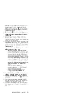
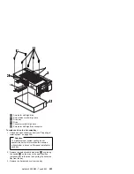
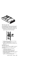
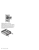

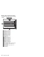
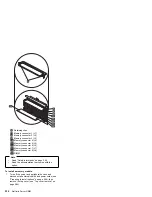
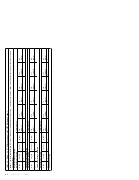
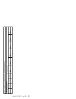
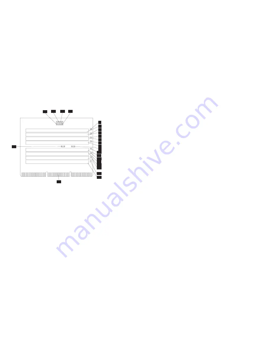
Memory board component locations
A layout of the memory board is shown in the following
illustration.
1
2
3
4
5
6
7
8
9
11
12
13
14
15
16
17
18
20
21
22
23
10
19
.1/
DIMM 1 error LED (CR5)
.2/
DIMM connector 1 (J1)
.3/
DIMM 2 error LED (CR6)
.4/
DIMM connector 2 (J2)
.5/
DIMM 3 error LED (CR3)
.6/
DIMM connector 3 (J3)
.7/
DIMM 4 error LED (CR2)
.8/
DIMM connector 4 (J4)
.9/
Reserved (J13)
.1ð/
DIMM 5 error LED (CR7)
.11/
DIMM connector 5 (J5)
.12/
DIMM 6 error LED (CR4)
.13/
DIMM connector 6 (J6)
.14/
DIMM 7 error LED (CR1)
.15/
DIMM connector 7 (J7)
.16/
DIMM 8 error LED (CR8)
.17/
DIMM connector 8 (J8)
.18/
Memory board connector to processor board
.19/
Reserved (might not be present) (J15)
.2ð/
Reserved (J12)
.21/
Reserved (might not be present) (J14)
.22/
Reserved (J9)
.23/
Reserved (J11)
230
Netfinity Server HMM
Summary of Contents for 866251Y - Netfinity 5500 M20
Page 2: ......
Page 8: ...vi Netfinity Server HMM...
Page 336: ...32 33 33 34 35 36 37 38 39 40 41 42 43 328 Netfinity Server HMM...
Page 346: ...338 Netfinity Server HMM...
Page 354: ...346 Netfinity Server HMM...
Page 355: ...Related service information 347...
Page 356: ...348 Netfinity Server HMM...
Page 357: ...Related service information 349...
Page 368: ...360 Netfinity Server HMM...
Page 369: ...Related service information 361...
Page 385: ......
Page 386: ...IBM Part Number 09N1015 Printed in U S A S37L 2 2 1...


