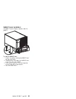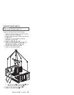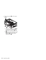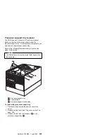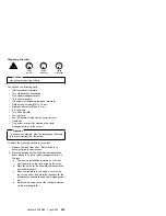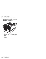
Preparing the rack:
Caution
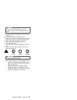
Use safe practices when lifting.
You will use the following parts:
IBM Installation Template
Two slide-bracket assemblies
One cable-management arm
Two bezel brackets
Six screws (for attaching the bezel brackets)
Sixteen long screws (M6 by 16 mm)
Eight short screws (M4 by 8 mm)
Six cage nuts
Two hex nuts (M6)
Four nut bars
Four lift handles (shipped with some servers)
Cable ties
One server bracket (for attaching the cable
management arm to the server)
Attention
To ensure rack stability, plan the installation of servers
in the rack starting from the bottom.
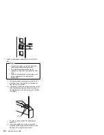
To attach the mounting hardware to the rack:
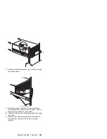
1. Remove the rack front door. Refer to the rack
documentation for instructions.
2. Mark the positions of the slide-bracket assemblies,
bezel brackets, and the cable-management arm on
the rack:
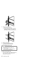
a. Position the installation template on the front
mounting rails on the rack, aligning the holes.
b. Mark the holes for the slide-bracket assemblies
and bezel brackets.
c. Move the template to the same U level at the
rear of the server and mark the locations for the
slide-bracket assemblies and cable-management
arm.
d. Install the six cage nuts at the locations marked
on the mounting rails.
k
18 kg
(37 lbs)
k
32 kg
(70.5 lbs)
k
55 kg
(121.2 lbs)
Netfinity 5500 M20 - Type 8662
263
Summary of Contents for 866251Y - Netfinity 5500 M20
Page 2: ......
Page 8: ...vi Netfinity Server HMM...
Page 336: ...32 33 33 34 35 36 37 38 39 40 41 42 43 328 Netfinity Server HMM...
Page 346: ...338 Netfinity Server HMM...
Page 354: ...346 Netfinity Server HMM...
Page 355: ...Related service information 347...
Page 356: ...348 Netfinity Server HMM...
Page 357: ...Related service information 349...
Page 368: ...360 Netfinity Server HMM...
Page 369: ...Related service information 361...
Page 385: ......
Page 386: ...IBM Part Number 09N1015 Printed in U S A S37L 2 2 1...

