

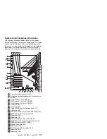
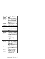
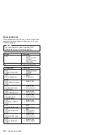
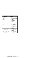
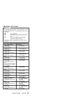

Table 18 (Page 2 of 2). System board jumpers
Jumper Name
Description
.1ð/
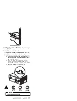
J32 Power-on
control with
extension cable
The default position is normal operation
(jumper on pins 1 and 2). Moving the jumper
to pins 2 and 3 allows the power supply to be
turned on without a power switch assembly or
Netfinity Advanced System Management
Processor. A cable is connected to these
pins to allow easy access while the processor
support tray is still installed; its white wire
indicates pin 1.
.11/
J15 RAID
download
The default is no jumpers on the pins. This
jumper block is used when the RAID adapter
EEPROM is being updated.
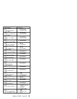
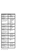
.12/
J25 Reserved
The default position is a jumper on pins 1 and
2.
.13/
J9 Reserved
The default position is a jumper on pins 1 and
2.
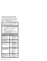
.2ð/
J34 Reserved
The default position is a jumper installed on
pins 1 and 2.
.21/
J29 Reserved
The default position is a jumper installed on
pins 1 and 2.
.22/
J26 RS-485
The default is no jumper installed on J26.
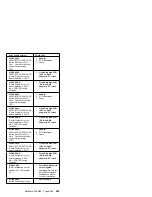
.24/
J51 Disable
Advanced System
Management
Processor
In normal operation, there is no jumper on
J51. Installing a jumper on J51 disables the
Netfinity Advanced System Management
Processor. A jumper should only be installed
on J51 for diagnostic purposes. Normal
operation of the server with J51 jumpered is
not supported.
A system operated in this manner is limited in
the following ways:
1. No system error logging.
2. No monitoring of system functions for
problem.
3. No automatic recovery after an NMI
error.
4. Error indication ability is severely limited.
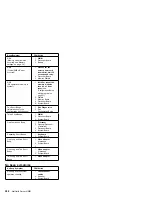
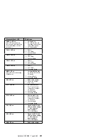
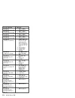
.27/
J24 Power-on
password override
Changing the position of this jumper bypasses
the power-on password check if the jumper
has been moved since the server was last
powered on. You do not need to move the
jumper back to the default position after the
password is overridden.
Changing the position of this jumper does not
affect the administrator password check if an
administrator password is set.
.28/
J30 Flash
ROM page swap
The default position is a jumper installed on
pins 2 and 3. Changing the position of this
jumper will change which of the two pages of
Flash ROM is used when the system is
started.
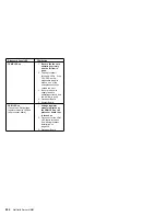
.46/
J5 Disable
Ethernet controller
The default position is Enabled (jumper on
pins 1 and 2). Move the jumper to pins 2 and
3 to disable the Ethernet controller.
.47/
J14 Disable
video controller
The default position is Enabled (jumper on
pins 1 and 2). Move the jumper to pins 2 and
3 to disable the video controller.
Netfinity 5500 M20 - Type 8662
281
Summary of Contents for 866251Y - Netfinity 5500 M20
Page 2: ......
Page 8: ...vi Netfinity Server HMM...
Page 336: ...32 33 33 34 35 36 37 38 39 40 41 42 43 328 Netfinity Server HMM...
Page 346: ...338 Netfinity Server HMM...
Page 354: ...346 Netfinity Server HMM...
Page 355: ...Related service information 347...
Page 356: ...348 Netfinity Server HMM...
Page 357: ...Related service information 349...
Page 368: ...360 Netfinity Server HMM...
Page 369: ...Related service information 361...
Page 385: ......
Page 386: ...IBM Part Number 09N1015 Printed in U S A S37L 2 2 1...


