background image


Ready drives and logical-drive slots still
available for the ServeRAID controller.

Ÿ

Configure for Clustering: This choice
is available in the Information mode
only. You can select this choice to
define the ServeRAID controller for use
in a high-availability, shared-disk cluster
environment. Detailed instructions for
using the clustering features are
provided in the 

IBM Netfinity

High-Availability Cluster Solution
Installation and User's Guide. You can
obtain a copy of this manual at the
following address on the World Wide
Web:

http://www.ibm.com/pc/us/
netfinity/clustering

Ÿ

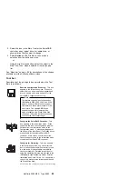
Initialize the Controller Configuration:
This choice is available in both the
Configuration and Information modes.
Select this choice to delete the
ServeRAID controller configuration.

  Attention 

After you initialize the controller
configuration, you will not have
access to any data stored on the
logical drives attached to the
selected ServeRAID adapter or
controller.

This choice deletes the existing
configuration information, sets all
functional hard disk drives attached to
the controller to the Ready state, and
deletes all logical drives defined for the
controller.

This choice 

does not change any of the

ServeRAID adapter or controller settings
(such as the stripe-unit size, rebuild rate,
and so on) from their current or
customized values.

Ÿ

Copy the Configuration from the
Drives to the Controller: 
This choice
is available in the Information mode
only; it copies the configuration
information stored on the hard disk
drives to the ServeRAID controller. This
function is useful when you import
previously configured drives from
another system, or when you replace
the ServeRAID adapter or controller.

88

Netfinity Server HMM 


Summary of Contents for 866251Y - Netfinity 5500 M20

Page 1: ...S37L 2020 01 IBM Netfinity Servers IBM Netfinity 5500 M20 Type 8662 Models 31Y 3RY 41Y 4RY 51Y 52G 5RY 61G 61Y 6RY Hardware Maintenance Manual June 1999 We Want Your Comments Please see page 372...

Page 2: ......

Page 3: ...S37L 2020 01 IBM Netfinity Servers IBM Netfinity 5500 M20 Type 8662 Models 31Y 3RY 41Y 4RY 51Y 52G 5RY 61G 61Y 6RY Hardware Maintenance Manual June 1999 We Want Your Comments Please see page 372 IBM...

Page 4: ...ation herein these changes will be incorporated in new editions of the publication IBM may make improvements and or changes in the product s and or the program s described in this publication at any t...

Page 5: ...o are familiar with IBM PC Server products Important safety information Be sure to read all caution and danger statements in this book before performing any of the instructions Leia todas as instru es...

Page 6: ...orld Wide Web WWW or the IBM PC Company BBS to download Diagnostic BIOS Flash and Device Driver files File download address is http www ibm com pc files html The IBM PC Company BBS can be reached at 9...

Page 7: ...tional service information 44 ServeRAID system board controller 66 Locations Removals 160 Symptom to FRU index 285 Undetermined problems 325 Parts listing Type 8662 327 Related service information 339...

Page 8: ...vi Netfinity Server HMM...

Page 9: ...data 23 PCI routing 23 Devices and I O ports 24 Date and time 25 System security 25 Using the power on password menu 26 Using the Administrator Password menu 28 Start options 29 Advanced setup 29 Cor...

Page 10: ...nstallation 60 Specifications 61 Status LEDs 63 Using the ServeRAID Advanced Configuration Functions 63 Setting the BootCd feature 64 ServeRAID system board controller 66 Understanding RAID technology...

Page 11: ...Copying the adapter configuration to the drives 114 Initializing the adapter 114 Scanning for new drives 115 ServeRAID monitoring functions 115 Monitoring adapter status information 115 Monitoring the...

Page 12: ...Installing ServerRAID device drivers for OpenServer 143 Installing the files for OpenServer 144 Adding BTLD at boot time 144 Adding BTLD after the initial installation 145 Using an IDE CD ROM drive to...

Page 13: ...ty between network adapters and device drivers 171 Battery replacement 173 Changing jumper positions 176 Two pin jumper blocks 176 Three pin jumper blocks 177 Completing the installation 178 Installin...

Page 14: ...8 Installing devices on the NetBAY3 base plate 229 Memory board component locations 230 Memory board jumpers 231 Memory board removal 232 Memory modules 234 Microprocessor installation 238 Preparing t...

Page 15: ...or symptoms 300 Power supply LED errors 301 POST error codes 304 SCSI error codes 311 ServeRAID controller error codes messages 312 ServeRAID POST error codes 314 ServeRAID POST error procedures 314 S...

Page 16: ...or message After the cause of the first error message is corrected the other error messages might not occur the next time you run the test A failed system might be part of a shared DASD cluster two or...

Page 17: ...OF A CLUSTER Yes No 002 Go to Step 004 003 Schedule maintenance with the customer Shut down all systems related to the cluster Run storage test 004 Power off the computer and all external devices Chec...

Page 18: ...nitor and access POST or to look at the System Error Log See Using remote video mode to monitor and access POST on page 58 006 Run the Diagnostic Programs If necessary refer to Running diagnostic prog...

Page 19: ...or by the software you can run the diagnostic programs to confirm that the hardware is working properly Note A single problem might cause several error messages When this occurs work to correct the ca...

Page 20: ...gle problem might cause several error messages When this occurs work to correct the cause of the first error message After the cause of the first error message is corrected the other error messages us...

Page 21: ...he operating system or both Messages are generally text messages but they also can be numeric For information about these error messages refer to the documentation that comes with the software System...

Page 22: ...keyboard USB mouse The USB mouse will not be used by diagnostics so with no mouse you will not be able to navigate between test categories directly using the Next Cat and Prev Cat buttons All other mo...

Page 23: ...evice tests assume that a keyboard and mouse are attached to the server Tips on the diagnostic programs 1 For system board tests first remove all installed adapters 2 Hard drive surface analysis can b...

Page 24: ...he Test Log For a list of error codes and messages see Symptom to FRU index on page 285 Viewing the test log If you are already running the diagnostic programs continue with step 4 in this procedure N...

Page 25: ...supported CD ROM Drive Standard 32X IDE Keyboard and Auxiliary Device standard only on tower models Keyboard Mouse Expansion Bays Six slim 1 inch or three half high 1 6 inch hot swap drive bays Three...

Page 26: ...AID controller two channels on system board 10BASE T 100BASE TX Ethernet port controller on system board Redundant Ethernet capability through the use of an optional network interface card NIC Netfini...

Page 27: ...e 21 Configuration Setup Utility main menu on page 22 Configuring options on page 32 Configuring ISA and PCI adapters on page 33 Resolving configuration conflicts on page 33 Configuring the ethernet c...

Page 28: ...ure system board functions such as serial and parallel port assignments change interrupt request IRQ settings and change the startup sequence for drives that you install You also can use this utility...

Page 29: ...vides a convenient way to display and change the settings After you run and exit from the Configuration Setup Utility program configuration information is stored in nonvolatile random access memory NV...

Page 30: ...ion 1998 F1 Help Move Esc Exit Enter Select System Summary System Information Devices and I O Ports Date and Time System Security Start Options Advanced Setup Plug and Play Error Logs Save Settings Re...

Page 31: ...stem information Select this choice to display information about the Netfinity 5500 M20 and to view the IRQ settings for the RAID and Ethernet controllers on the system board and other PCI adapters th...

Page 32: ...adapter for information about port assignments You can configure the parallel port as bidirectional that is so that data can be both read from and written to a device In bidirectional mode the server...

Page 33: ...o levels of password protection Implementing these security measures helps you to ensure the integrity of the data and programs that are stored in the server After you set a power on password you can...

Page 34: ...Utility main menu Power on password only You must enter the password to complete the system startup You can access all the choices on the Configuration Setup Utility main menu Administrator password...

Page 35: ...ery replacement on page 173 and then reinstall the battery To delete a power on password 1 Select Power on Password from the System Security menu then press Enter The Power on Password menu appears 2...

Page 36: ...ain data field and type the password again Note A message appears if the two passwords do not match If this happens press Esc to cancel the request and return to the System Security menu 4 Select Chan...

Page 37: ...OST in the enhanced mode or the quick mode Select Start Options then use the Left Arrow or Right Arrow key to advance through each data field The Start Options choice appears only on the full Configur...

Page 38: ...the IRQ settings displayed in the PCI Routing selection of the System Information menu until you restart the server Memory settings Select this choice to manually disable or enable a row of memory If...

Page 39: ...lds These values range from 0 through 15 The Plug and Play choice appears only on the full Configuration Setup Utility main menu Note For further details about Plug and Play devices see Plug and Play...

Page 40: ...want to make the changes or exit without making the changes Configuring options Before installing a new device or program read the documentation that comes with it Reading the instructions helps you t...

Page 41: ...y 5500 M20 uses a rotational interrupt technique to configure PCI adapters This technique enables you to install a variety of PCI adapters that currently do not support sharing of PCI interrupts Resol...

Page 42: ...ings are incorrect or set to use a resource that cannot be shared a conflict occurs and the device will remain deactivated by the configuration program 4 Remove the device or adapter Some configuratio...

Page 43: ...duplex HDX and full duplex FDX modes at both speeds However auto negotiation works only if the hub or switch at the other end of the network also supports auto negotiation If the hub or switch does no...

Page 44: ...for the operating system before you use the Ethernet controller The Ethernet controller supports the auto detection mode only When you install the device drivers and configure the Ethernet controller...

Page 45: ...e Category 5 or higher to meet various standards including electromagnetic compatibility The cables used in 10BASE T or 100BASE TX link segments do not require grounding However all devices connected...

Page 46: ...s the RJ 45 connector 10BASE T or 100 BASE TX UTP Cable RJ 45 Modular Plug Connector 1 2 3 Pins 6 The following figure illustrates the wiring in straight through cables Twisted Pair 1 2 3 6 4 5 7 8 RJ...

Page 47: ...u are not using a hub with X ports use a crossover cable To determine whether a hub has an X port check the port label If the label contains an X the hub has an X port If the ethernet adapter cannot c...

Page 48: ...to an operational state the Ethernet traffic automatically switches back to the primary Ethernet controller Note that only one controller in the redundant pair is active at any given time For example...

Page 49: ...r is located in slot E PCI primary bus 0 slot 14 5 To enable the writing of messages to the IBMCOM LANTRAN LOG file when a failover occurs a Copy the file PCNETOS2 EXE from the root directory of the d...

Page 50: ...er is located and x and y are the PCI slot numbers where the redundant pair is located The slot number associated with the integrated Ethernet controller can vary depending upon the configuration of t...

Page 51: ...tomatically switch back to the primary adapter when the primary adapter comes back online In this case issue the command LOAD d path PCNTNW SCAN where d and path are the drive and path where the drive...

Page 52: ...power on password on page 45 Ethernet subsystem error messages on page 45 Light path diagnostics on page 48 Netfinity Advanced System Management Processor on page 52 Software installation on page 60 S...

Page 53: ...messages may be displayed if Network is selected in the startup sequence of the configuration program 2 The following error messages are available only with the integrated Ethernet subsystem These err...

Page 54: ...net controller EEPROM is faulty or not present RPL ROM ERR 106 The integrated Ethernet controller is configured for Plug and Play in a non Plug and Play system RPL ROM ERR 110 The integrated Ethernet...

Page 55: ...annot read from TFTP connection M40 BOOTP canceled by keystroke M40 DHCP canceled by keystroke M41 BOOTP timeout M41 DHCP timeout M42 No client or server Internet protocol IP address M43 No boot start...

Page 56: ...m if an error causes the server to shut down The light path diagnostics begin with the System Error LED on the information LED panel See the illustration in Information LED panel on page 205 When this...

Page 57: ...termine if it is failing by removing the adapter from the PCI primary bus 0 PCI slot 5 and restarting the server If the problem persists go to General checkout on page 8 PCI 2 LED on An error occurred...

Page 58: ...n Action Replace fan 2 FAN 3 LED on Fan 3 has failed or is operating too slowly Note A failing fan can also cause the TEMP and DASD1 LEDs to be on Action Replace fan 3 FAN 4 LED on Fan 4 has failed or...

Page 59: ...cated in the log check fans 2 Turn off the server reseat the microprocessor indicated by the lit Microprocessor Error LED and restart the server 3 If the problem persists replace the microprocessor 4...

Page 60: ...nced System Management Processor that is integrated in the Netfinity 5500 M20 It also describes how to access the Netfinity Advanced System Management Processor without Netfinity Manager Note To use a...

Page 61: ...or the Advanced System Management Service with Netfinity Manager The minimum system requirements for using the Advanced System Management service are Netfinity Advanced System Management Processor bui...

Page 62: ...you have established a connection with the Netfinity Advanced System Management Processor you will be prompted for a username and password You must provide a username and password combination that ha...

Page 63: ...ings voltage regulator module readings fan status redundant power supply status Error Logs Contents of System Error Log Service Processor Configuration Netfinity Advanced System Management Processor m...

Page 64: ...you will be prompted for a username and password You must provide a username and password combination that has been previously configured for use with the Netfinity Advanced System Management Processo...

Page 65: ...tly powered on Boot menu selections You can use the selections available from the Boot menu to Shutdown the server operating system and then restart the server Restart the server immediately without f...

Page 66: ...Boot menu appears 1 Reboot w OS Shutdown 2 Reboot immediately 3 Restart SP 4 Select a Boot menu item Select 1 Reboot w OS Shutdown to shutdown the server operating system and then restart the server S...

Page 67: ...l caps and the 0 in PASSW0RD is the numeral zero A username and password that you define using the Advanced System Management service and Netfinity Manager Important If you update the Netfinity Advanc...

Page 68: ...n the Netfinity Advanced System Management Processor all textual output generated during POST will be sent to the terminal window The terminal will also act as a fully active remote session enabling y...

Page 69: ...6 lb Unpacked maximum configuration 55 4 kg 111 lb Heat Output Approximate heat output in British thermal units Btu per hour Minimum configuration 1023 9 Btu Maximum configuration 2764 6 Btu Environme...

Page 70: ...6 EMCA 109 The declared sound power levels indicate an upper limit below which a large portion of machines operate Sound pressure levels in your location might exceed the average 1 meter values stated...

Page 71: ...board See Memory board component locations on page 230 for locations of the LEDs on the memory board Using the ServeRAID Advanced Configuration Functions The Advanced Functions choice allows you to i...

Page 72: ...plays the ServeRAID controller hardware and PCI register information as shown in the following example screen Press any key to continue IBM ServeRAID Adapter Disk Array Mini Configuration Utility Ver...

Page 73: ...ROM Press Enter to change No to Yes This also changes No to Yes next to Display Boot CD ROM Menu and BIOS Support for INT13 Extensions 2 Ensure that the screen displays Yes next to BIOS Support for r...

Page 74: ...gram using on page 119 ServeRAID IPSMON program starting on page 128 ServeRAID IPSMON program using on page 128 ServeRAID device drivers and utility programs installation on page 130 Administration an...

Page 75: ...ripe unit size With RAID technology data is striped across an array of hard disk drives This data distribution scheme complements the way the operating system requests data The granularity at which da...

Page 76: ...es assigned RAID level 1 or level 5 in the same array they will not lose data Note The ServeRAID controller automatically assigns RAID level 0 to all logical drives in an array containing only one har...

Page 77: ...RAID level 1 the ServeRAID controller automatically assigns the IBM Enhanced RAID level 1 to the array The Enhanced RAID level 1 combines mirroring with data striping This RAID level stripes data and...

Page 78: ...ives The logical drive is assigned RAID level 5 Notice that the storage of the data parity also is striped and it shifts from drive to drive Data Stripe 1 Block 1 Block 2 Block 3 Mirror Stripe 1 Block...

Page 79: ...the ServeRAID controller array logical drive hot spare drive or physical drive objects from this Main Tree 4 Main Panel Provides specific device information or configuration instructions When the conf...

Page 80: ...n page 78 for more information The ServeRAID Configuration Program is provided on the IBM ServeRAID Configuration CD packaged with the ServeRAID adapter and it also is provided on the ServerGuide CD C...

Page 81: ...ntrollers in the server are configured the program starts in the Information mode and a screen similar to the following appears IBM ServeRAID Configuration Program Controller 1 Information File View A...

Page 82: ...ee arrays and one hot spare drive as follows Array A The total capacity of this array is 1024 MB 1x1024 MB and it contains one 1024 MB RAID level 0 logical drive Array B The total capacity of this arr...

Page 83: ...ServeRAID subsystem Using this path you can select the drives that you want to include in each array define the number and size of the logical drives for each array and select the drives that you wan...

Page 84: ...nd one 1 GB drive into an array the total capacity of that array is 4 GB not the 7 GB physically available A hot spare drive is a disk drive that is defined for automatic use in the event of a drive f...

Page 85: ...en select Remove from New Array or Delete New Array Remove a specific hot spare drive or all newly defined hot spare drives To do this select the Back button use the right mouse button to select the H...

Page 86: ...eRAID device drivers and utility programs Information mode You can use the Information mode to view the configuration information for the server ServeRAID controllers arrays logical drives hot spare d...

Page 87: ...the current setting of 8 KB 16 KB 32 KB or 64 KB for the stripe unit size See Interleave depth and stripe unit size on page 67 and page 90 for more information Rebuild Rate shows the current setting H...

Page 88: ...g information appears in the Main Panel on the right Array Letter shows the letter A through H assigned to the array Array Size in MB shows the total size in MB of the array Free Space in MB shows the...

Page 89: ...from the Main Tree the following information appears in the Main Panel on the right SCSI ID shows the SCSI ID assigned to the drive Channel shows the SCSI channel to which the hot spare drive is attac...

Page 90: ...the drive manufacturer Product or Model Number shows characters that represent the product or model number for the drive Serial Number shows the serial number for the drive Drive Firmware Level shows...

Page 91: ...rveRAID controller uses this reserved state during a logical drive migration LDM Critical A RAID level 1 or level 5 logical drive that contains a defunct physical drive is in the critical state A crit...

Page 92: ...properly 4 Each device on the SCSI channel has its own unique SCSI ID If the hard disk drive still does not function after you perform these steps replace the drive Empty No device is present in the...

Page 93: ...ted BIOS code needed to support this feature will be made available on the World Wide Web See page 130 for the instructions needed to access the IBM support page Configure the ServeRAID Controller Thi...

Page 94: ...anel on the right Options Select this choice to change the Initialization and Synchronization mode as follows Scan for New or Removed Ready Drives This icon appears in the Information mode When you se...

Page 95: ...t initialize each logical drive by writing zeros to the first 1024 sectors of the logical drive when it is created You still must initialize all newly defined logical drives before storing data If you...

Page 96: ...uration Attention After you initialize the controller configuration you will not have access to any data stored on the logical drives attached to the selected ServeRAID adapter or controller This choi...

Page 97: ...the Information mode only You can select this choice to set the priority for Rebuild operations to High default Medium or Low When the rebuild rate is set to High the rebuild I O request gets high pri...

Page 98: ...Information mode if you select the Arrays icon and Ready drives are available When you select this choice the configuration program switches from the Information mode to the Configuration mode Delete...

Page 99: ...st operation before you turn off the system Failure to follow this practice can result in lost data Synchronize This choice is available in the Information mode when you select a logical drive from th...

Page 100: ...in Tree Remove from Hot Spare State This choice is available in the Information mode only Select this choice to remove a hot spare drive from the configuration and set the drive state back to Ready Th...

Page 101: ...Information mode only Select this choice to physically replace a defunct disk drive Note Always replace a defunct drive with a drive of equal or greater capacity Scan for New or Removed Ready Drives...

Page 102: ...Main Menu appears Descriptions of the choices available from the Main Menu of the Mini Configuration program are as follows View Controller Status shows the current status of the ServeRAID adapter or...

Page 103: ...Number of Defunct Drives shows the current number of Defunct physical drives Number of Offline Drives shows the current number of Offline logical drives Number of Critical Drives shows the current num...

Page 104: ...selected ServeRAID adapter or controller This choice deletes the existing configuration information sets all functional hard disk drives attached to the controller to the Ready state and deletes all l...

Page 105: ...ROM feature When you attach a CD ROM drive to the ServeRAID adapter or controller and set the Bootable CD ROM feature to Yes the ServeRAID adapter or controller will attempt to start a CD that has a...

Page 106: ...ebuild an array create a logical drive create an array delete an array dynamically increase the logical drive size change RAID levels and much more Starting the ServeRAID Administration and Monitoring...

Page 107: ...n stand alone mode After this program loads you can access the ServeRAID adapters and controllers When the Main window appears If you are running the program in the stand alone mode and you have Serve...

Page 108: ...he Tool Bar or select Network Settings from the Options pull down menu A screen similar to the following appears 2 Select the Client Server radio button 3 If security is enabled on the server to which...

Page 109: ...ing appears You can use this screen to Enable or Disable the alarm Reset the alarm Set the polling options Enabling or disabling the alarm The alarm alerts you to a failure in the system It sounds if...

Page 110: ...completed Synchronization started Synchronization completed Migration started Migration completed PFA error detected Dead drive detected Adapter or controller is not responding to commands Alert optio...

Page 111: ...rning PFA error detected c Fatal Dead drive detected Adapter or controller is not responding to commands By knowing what these types of messages are you can configure the Netfinity Manager program wit...

Page 112: ...select a RDY drive click the desired RDY button from the device area A disk array identifier appears beside each RDY drive added to the disk array If you change your mind about a selected drive select...

Page 113: ...t be slightly different from what you type in the Requested Space field The RAID level and the number of hard disk drives determine the size of the logical drive For example a disk array consisting of...

Page 114: ...ing information to create logical drives initialize and synchronizing logical drives or access blocked logical drives Creating logical drives To create a logical drive 1 Select the icon on the Tool Ba...

Page 115: ...rives determine the size of the logical drive For example a disk array consisting of three 1 GB hard disk drives with a requested RAID level 0 logical drive of 1000 MB will actually contain only 999 M...

Page 116: ...the data redundancy for the logical drive is correct To synchronize a logical drive 1 Select the desired logical drive from the Main screen of the Administration and Monitoring Program 2 Select Synchr...

Page 117: ...t have at least two logical drives available one free FRE logical drive and one source logical drive that is in the okay OKY state During the LDM procedure the ServeRAID adapter or controller changes...

Page 118: ...Select OK to verify the operation 7 Select a Ready RDY drive to add to the array if you are migrating to RAID level 5 Adding a physical drive The ServeRAID adapters and controllers support adding new...

Page 119: ...he following illustration 500 MB 1000 MB 2800 MB Disk 1 Disk 2 Before LDM Disk 3 750 MB 1500 MB 4200 MB Disk 1 Disk 2 After LDM Disk 3 Disk 4 Logical Drive 0 Logical Drive 1 Free Space Logical Drive 0...

Page 120: ...ates To set or change the physical device state 1 Select the device from the Main screen of the Administration and Monitoring Program 2 Select the radio button that indicates the desired state Note If...

Page 121: ...pter or controller can perform only one Rebuild operation at a time 2 If the array contains a critical CRT logical drive the Rebuild operation changes the hard disk drive state from DDD to RBL After t...

Page 122: ...Tool Bar or select Adapter Configuration from the Advanced pull down menu A screen similar to the following appears 2 Select Copy Adapter Configuration to Drives 3 Select OK Initializing the adapter...

Page 123: ...choice does not change any of the ServeRAID adapter or controller settings such as the stripe unit size rebuild rate and so on from their current or customized values 3 Select OK Scanning for new dri...

Page 124: ...is a ServeRAID startup error Code Block Version The current version number of the firmware loaded on the adapter or controller Boot Block Version The current version number of the bootable microcode l...

Page 125: ...and reported to the ServeRAID adapter or controller through the SCSI Check Condition status Predictive Failure Analysis PFA The device has signaled the adapter or controller that it might fail in the...

Page 126: ...pe Unit Size The size of each stripe unit per hard disk 8 16 32 64 Number of Chunks The number of hard disk drives that make up the logical drive Stripe Order The channel and SCSI ID of the physical d...

Page 127: ...ram from the operating system command line To start the IPSSEND program If you are using OS 2 or Windows NT 1 Type c ipsadm ipssend 2 Press Enter Note The c represents the drive where OS 2 or Windows...

Page 128: ...and UnixWare Command IPSSEND BACKUP Controller Filename Oparm Replace Controller with the ServeRAID controller number 1 to 8 Filename with the path and file name where the configuration is to be writ...

Page 129: ...t INIT Use the INIT command to initialize the first 0 5 MB of a logical drive This process will erase the partition tables on the drive and all data on the logical drive will be lost Supported operati...

Page 130: ...ds The IPSSEND error recovery commands include the following GETSTATUS Use the GETSTATUS command to display the current logical drive status for the most recent rebuild synchronization or logical driv...

Page 131: ...new state Attention You must be very careful when you use this command For example you might lose data if you reset a Defunct DDD device to Online ONL without first performing a Rebuild operation Supp...

Page 132: ...e ServeRAID controller number 1 to 8 DriveNum with the logical drive number 0 to 7 ServeRAID problem isolation and debug commands The IPSSEND problem isolation and debug commands include the following...

Page 133: ...r 1 to 8 Channel with the channel number for the device 1 2 or 3 SID with the SCSI ID for the device 0 to 15 FORMAT Use the FORMAT command to perform a low level format of a hard disk drive Attention...

Page 134: ...ller Options Replace Controller with the ServeRAID controller number 1 to 8 Options with one of the following DEVICE for Device Event Log SOFT for the ServeRAID adapter or controller Soft Event Log or...

Page 135: ...Channel SID Replace Controller with the ServeRAID controller number 1 to 8 Channel with the channel number for the device 1 2 or 3 SID with the SCSI ID for the device 0 to 15 GETCONFIG Use the GETCON...

Page 136: ...e IPSMON program If you are using OS 2 or Windows NT 1 Type c ipsadm ipsmon 2 Press Enter Note The c represents the drive where OS 2 or Windows NT is installed If you are using Novell NetWare 1 From t...

Page 137: ...OpenServer or UnixWare press the Del key to cancel the program During operation the program will log various messages Each message will contain an alert code and a location specifier The alert code be...

Page 138: ...ServeRAID device drivers and utility programs available from the IBM Support page on the World Wide Web In addition to the updated device drivers and utility programs there are also two ServeRAID comm...

Page 139: ...ete an array create a logical drive change the RAID level dynamically increase the logical drive size rebuild an array and perform other basic ServeRAID configuration functions You can run the WIN32 B...

Page 140: ...gram and they install automatically when you use the instructions in this chapter to install the ServeRAID device driver for OS 2 or NetWare A good way to use these operating system specific programs...

Page 141: ...r OpenServer operating system Use the instructions in this section to install the WIN32 Based program on the Windows 95 client If the network operating system is OS 2 NetWare OpenServer or UnixWare yo...

Page 142: ...onitoring Program files and background server components install automatically when you use the instructions in this section to install the ServeRAID device drivers for OS 2 and NetWare The Windows NT...

Page 143: ...the diskette drive then press Enter 7 Select IBM ServeRAID Adapter then press Enter A message similar to the following will appear Setup is loading files IBM ServeRAID Adapter 8 When prompted press En...

Page 144: ...e diskette to copy all required files to the server directory The INSTALL BAT file will modify the STARTUP NCF file so that it will load the required NetWare modules Use the instructions provided in t...

Page 145: ...Ware modules Use the instructions provided in the NetWare 3 12 manual along with the following instructions to install the ServeRAID device driver background server component and Administration and Mo...

Page 146: ...te into the diskette drive 4 Select Select additional or modify selected Disk LAN drivers 5 If IPSRAID appears select Deselect a selected driver 6 Select Select an additional driver then press the Ins...

Page 147: ...assumes that you installed NetWare in its default directory If you did not install NetWare in the NWSERVER directory on drive C modify step 13 accordingly 2 If any of the files you are installing alre...

Page 148: ...aiting 10 seconds or longer gives the ServeRAID adapter or controller the time needed to flush all dirty cache pages out to the hard disk To install the ServeRAID files while installing OS 2 1 Use the...

Page 149: ...the line BASEDEV IPSRAID ADD Notes 1 If you have more than one ServeRAID or SCSI adapter in the system make sure that the BASEDEV statement for the adapter controlling the startup boot device appears...

Page 150: ...y the device driver files 6 Select Install The program copies the following ServeRAID device driver statement to the CONFIG SYS file BASEDEV IPSRAID ADD The program copies the following ServeRAID devi...

Page 151: ...ers field type lf d path logfile e At the General Tab in the Title field type ServeRAID Installing ServerRAID device drivers for OpenServer To use the ServeRAID Administration and Monitoring Program w...

Page 152: ...e SCSI ID and the LUN respectively 2 When prompted for the location of the installation CD change the Bus Number and SCSI ID as required Adding BTLD at boot time To install the ServeRAID device driver...

Page 153: ...ess Enter then relink the kernel as described in Relinking the kernel in the SCO OpenServer Handbook by entering the following commands cd etc conf cf d link_unix 8 After the kernel rebuilds the follo...

Page 154: ...roller d master 0 or slave 1 device l LUN of device always 0 with ATAPI or wd driver b BUS of device always 0 with ATAPI or wd driver 2 Let the system start normally until it comes to the select Media...

Page 155: ...are on a ServeRAID drive Use the following instructions if you are using multiple disk storage adapters or controllers and you are installing UnixWare on a drive attached to a ServeRAID adapter or con...

Page 156: ...he SCSI cable from the ServeRAID connector on the system board See the label inside the server cover for the location of the ServeRAID connector 5 Remove all other non ServeRAID IDE and SCSI disk stor...

Page 157: ...ntrollers 1 Install all ServeRAID adapters that you intend to use in the system 2 Using the ServeRAID Configuration Program create all of the arrays and define all of the logical drives 3 Make a list...

Page 158: ...r from the list you created in step 3f on page 149 then attach the drives to the ServeRAID adapter or controller 9 Turn on the system and allow UnixWare to discover the new disk storage adapters and c...

Page 159: ...driver installs restart the system Installing an HBA diskette file using SCOAdmin 1 Use the ServerGuide Diskette Factory to create an IBM ServeRAID Device Drivers for SCO Operating Systems Diskette 2...

Page 160: ...rver components This section provides information about background server component command line parameters and logging messages Command line parameters To use the command line parameters provided in...

Page 161: ...can have these messages logged to other output devices such as a printer or a text file The following information provides examples of different formats for using the IPSADM command and the results C...

Page 162: ...configuration or inability to access the DNS If problems persist check the network configuration IPSSEND and IPSMON programs IPSSEND and IPSMON are advanced command line programs that you can use to m...

Page 163: ...directory on the hard disk drive To do this go to the operating system command prompt and type md c ipsadm Notes 1 The c represents the drive where OS 2 or Windows NT is installed 2 If you installed...

Page 164: ...ring Program on page 98 for information to start and use the IPSSEND and IPSMON programs Installing IPSSEND and IPSMON for OpenServer To install these programs for OpenServer 5 0 X 1 Insert the IBM Se...

Page 165: ...diskette drive A then type format a s 2 Press Enter 3 Copy the ASPI device driver from the DOS directory on the IBM ServeRAID Device Driver Diskette to the startable diskette 4 Copy the IPSSEND EXE fi...

Page 166: ...ve with RAID level 0 is lost during the rebuild operation If you backed up the data before the drive failed you can restore the data to the new drive General information about the rebuild operation A...

Page 167: ...no hot spare or standby hot spare drives are available the rebuild operation will start the moment you replace the defective drive Note If you physically replace the drive and the new drive does not...

Page 168: ...in the NetBAY3 on page 225 Memory board component locations on page 230 Memory board jumpers on page 231 Memory board removal on page 232 Memory modules on page 234 Microprocessor installation on page...

Page 169: ...CI slot supports only a short adapter The expansion slots have Plug and Play capabilities See Plug and Play technology on page 164 for additional information The server comes with a video controller T...

Page 170: ...LED is on When this LED is off the PCI slot is inactive and has no power applied An adapter can be installed when the Power LED for the PCI slot is off Refer to the operating system documentation to...

Page 171: ...adapters can also be installed in these slots The server supports 5 0V and universal PCI adapters it does not support 3 3V adapters Note A universal PCI adapter supports both 3 3V and 5 0V operation...

Page 172: ...the server during startup This information is read by the input output I O bus and interpreted by the server BIOS The BIOS routines automatically configure the adapter around the resources already in...

Page 173: ...e IBM Web site at http www ibm com support Select Intel Processor Based Servers Support From the Select family field select Netfinity 5500 M20 Select Downloadable files Attention All hot plug operatio...

Page 174: ...g adapter before performing the operating system defined procedure for disabling the hot plug PCI slot that contains the adapter Failure to do so might cause the system to lock up Refer to the operati...

Page 175: ...PCI adapters 3 Disable the selected PCI slot from the operating system Refer to the documentation that comes with the operating system for information about disabling a hot plug PCI slot Disabling the...

Page 176: ...7 by its top edge or upper corners and align it with the expansion slot on the system board b Press the adapter firmly into the expansion slot Attention When you install an adapter in the server be s...

Page 177: ...to remove a non hot plug adapter reverse the steps Note Read Safety information on page 340 Read the documentation that comes with the option Refer to the following illustration while you perform the...

Page 178: ...use If you are installing an adapter in PCI slot 5 or in the ISA slot a Remove the screw 1 on the top of the expansion slot cover 2 b Slide the expansion slot cover out of the server c Store these ite...

Page 179: ...ded notch in the retaining bracket on the adapter 5 with the threaded hole in the expansion slot frame The retaining bracket on the adapter fits into the space that was occupied by the expansion slot...

Page 180: ...t the network adapter device driver supports up to four processors Refer to the network adapter documentation for additional information about adapter compatibility requirements 172 Netfinity Server H...

Page 181: ...dinances or regulations Note In the U S call 1 800 IBM 4333 for information about battery disposal If you replace the original lithium battery with a heavy metal battery or a battery with heavy metal...

Page 182: ...Use one finger to slightly slide the battery toward the rear of the server The spring mechanism behind the battery will push it out toward you as you slide it forward c Use your thumb and index finger...

Page 183: ...the Configuration Setup Utility program and set configuration parameters as needed To set the system date and time go to Date and time on page 25 To set the power on password go to Using the power on...

Page 184: ...nly or remove the jumper entirely The following illustration identifies pins 1 and 2 on a two pin jumper block 2 1 To change a jumper s position for a two pin jumper block 1 Turn off the server then d...

Page 185: ...on a three pin jumper block 2 1 3 To change a jumper s position for a three pin jumper block 1 Turn off the server then disconnect the server power cords 2 Remove the server cover see Preparing to ins...

Page 186: ...ds of time over 30 minutes with the top cover removed might damage server components Installing the top cover Refer to the following illustration while you perform the steps in this procedure 1 Thumbs...

Page 187: ...nnect the telephone line after you plug in the power cords 2 If necessary see Input output connectors and expansion slots on page 209 for connector locations Installing the trim bezels and server door...

Page 188: ...hen you start the server for the first time after you add or remove an internal option or an external SCSI device you might see a message telling you that the configuration has changed Some options ha...

Page 189: ...shes per second the controller is identifying the drive 3 Hard Disk Activity Light Each of the hot swap drive bays has a Hard Disk Activity light When this green light is flashing the drive is being a...

Page 190: ...to wait approximately 20 seconds before pressing the Power Control button If the server is activated and a power failure occurs the server will start automatically when power is restored The server ca...

Page 191: ...erver power cords from the electrical outlets to shut off all power to the server Note Wait about 15 seconds after disconnecting the power cord for the system to stop running Watch for the System Powe...

Page 192: ...lustration shows the front of the CD ROM drive CD ROM Drive In Use Light Emergency Eject Hole Eject Load Button Handling a CD When handling a CD follow these guidelines Hold the CD by its edges Do not...

Page 193: ...ton When the tray slides out carefully remove the CD 5 Close the tray by pressing the Eject Load button or by gently pushing the tray forward Note 1 If the tray does not slide out of the drive when yo...

Page 194: ...over see Top cover removal on page 284 2 To access the cable s attached to the DASD backplane slide the shuttle to the rear of the system see Shuttle removal on page 277 3 Disconnect the DASD backplan...

Page 195: ...th diagnostics on page 48 for information on identifying problems using these LEDs SMI NMI PCI1 PCI2 PS2 MEM FAN1 FAN2 FAN3 FAN4 TEMP VRM CPU DASD1 DASD2 PS1 CPU WRONG SLOT Speaker To replace the diag...

Page 196: ...986 SCSI X3 131 1994 SCSI 2 X3T10 1071D Adhering to these standards ensures that the server operates properly Setting SCSI IDs for external devices Each SCSI device that is connected to a SCSI control...

Page 197: ...of characters at any time with no restriction on the duration of the pauses between characters The serial ports can transmit and receive data and commands at rates of from 300 bits per second up to 11...

Page 198: ...tor on the back of the server It support three standard IEEE 1284 modes of operation Standard Parallel Port SPP Enhanced Parallel Port EPP and Extended Capability Port ECP See Input output connectors...

Page 199: ...gnments for the video connector Keyboard and auxiliary device ports The system board has one keyboard port and one auxiliary device port that supports a mouse or other pointing device See Input output...

Page 200: ...ata 2 Not connected 3 Ground 4 5 V dc 5 Clock 6 Not connected Table 7 68 pin SCSI port connector pin number assignments Pin Signal Pin Signal 1 Ground 35 Data 12 2 Ground 36 Data 13 3 Ground 37 Data 1...

Page 201: ...orts The system board in the Netfinity 5500 M20 contains two universal serial bus USB ports Each USB port has an external connector on the rear on the server for attaching devices that previously used...

Page 202: ...ment Processors of several servers mounted in a rack enclosure to communicate with each other in half duplex mode Table 10 shows the pin number assignments for the RS 485 connector 1 6 Table 9 USB con...

Page 203: ...on page 284 2 Remove the door and trim bezel see Server door and trim bezels removal on page 276 3 Remove the side covers see Side cover s removal on page 278 4 Remove the front bezel a While releasi...

Page 204: ...page 250 for details Caution Never remove the cover on a power supply or any part that has the following label attached Hazardous voltage current and energy levels are present inside any component th...

Page 205: ...Filler panel 3 Power supply 4 Power cord strain relief bracket 5 Hole for shipping thumbscrew 6 Handle 7 AC Power light 8 Power cord connector for power supply 2 9 DC Power light Netfinity 5500 M20 T...

Page 206: ...from the filler panel b Remove the filler panel 2 from the power supply bay and save it and the four screws you removed Note During normal operation each power supply bay must have either a power sup...

Page 207: ...f the power cord to an easily accessible power source 5 Install a power cord strain relief bracket 4 if desired 6 Plug the power cord into a properly grounded electrical outlet 7 Verify that the dc Po...

Page 208: ...ver remove the cover on a power supply or any part that has the following label attached Hazardous voltage current and energy levels are present inside any component that has this label attached There...

Page 209: ...e 6 on the power supply in the open position and slide the power supply into the chassis b Gently close the handle 6 on the power supply to seat the power supply in the bay c Verify that the ac Power...

Page 210: ...oper cooling Note You do not need to turn off the power to the server to replace a hot swap fan assembly The following illustrations show the replacement of a hot swap fan assembly Refer to these illu...

Page 211: ...ury disconnect the hot swap fan cables before removing the fan from the device 1 Remove the top cover see Top cover removal on page 284 Attention To ensure proper system cooling do not remove the top...

Page 212: ...ed the processor support tray cover 1 install it and turn the two quarter turn fasteners 2 one quarter turn to secure the cover g Connect the fan power cable 3 to the power connector 4 If fan assembly...

Page 213: ...cal current from the server you must unplug the server power cords from the electrical outlets 2 System POST Complete Light This green light is on when the power on self test POST completes without an...

Page 214: ...his green light is on there is an active connection on the Ethernet port 8 Ethernet Speed 100 Mbps When this green light is on the Ethernet speed is 100 Mbps When this light is off the Ethernet speed...

Page 215: ...rmation LED panel cover a Place your fingers inside the right side of the cover near the latch tab 1 b Move the end of the cover away from the right side of server until the latch tab 1 on the cover i...

Page 216: ...the top cover see Top cover removal on page 284 3 Remove the side covers see Side cover s removal on page 278 4 Remove the front bezel leaving the information LED panel cover attached See Front bezel...

Page 217: ...provide bus master capabilities which enable the adapters to perform operations without interrupting the system microprocessors 3 Parallel Connector A signal cable for a parallel device such as a prin...

Page 218: ...u can install devices such as the IBM EXP10 or a power distribution unit in the NetBAY3 Refer to Installing devices in the NetBAY3 for more information 1 Management C Connector This connector is used...

Page 219: ...or The mouse cable connects here This port sometimes is called an auxiliary device or pointing device port 17 Management RS 485 Connector This connector is for connecting rack or multirack systems thr...

Page 220: ...do the following 1 Remove the top cover see Top cover removal on page 284 2 Disconnect the cable 3 attached to interior LED and speaker assembly 1 3 Remove the interior LED and speaker assembly 1 a R...

Page 221: ...and one CD ROM drive 1 Bay 1 2 Bay 2 3 Bay 3 4 Bay 4 5 Bay 5 6 Bay 6 7 Hot swap bays 8 Removable media bays 9 Bay B 1 Bay A 11 CD ROM drive bay 12 Diskette drive bay The server contains hardware that...

Page 222: ...0 supports only one diskette drive The server does not support hard disk drives in bays A and B because of cooling considerations Note The server s EMI integrity and cooling are both protected by havi...

Page 223: ...e 279 This cable goes to the external SCSI connector on the back of the server so you will not be able to attach external SCSI devices using the external SCSI connector Use the 16 bit SCSI cable to co...

Page 224: ...e removable media drive bays has a terminator at the other end For example when you install a SCSI device in a removable media drive bay bay A or B set its termination to Disable because the SCSI cabl...

Page 225: ...cumentation that comes with the drive Prepare the drive for installation see Preinstallation steps all bays on page 216 Note The server s EMI integrity and cooling are both protected by having the lef...

Page 226: ...1 and filler panel 2 from the bay opening Save screws for later use in this procedure You do not need the filler panel when you have a drive installed in the bay 4 Touch the static protective bag con...

Page 227: ...Processor support tray removal on page 259 b Disconnect the cable from the RAID channel 1 connector on the system board See System board component locations on page 279 for the location of the RAID c...

Page 228: ...he documentation that comes with the drive Review ServeRAID system board controller on page 66 for information about the RAID controller and disk array configuration Prepare the drive for installation...

Page 229: ...he disk arrays after installing hard disk drives Replacing a drive in a hot swap bay You do not have to turn off the server to remove a drive from the hot swap bays Attention 1 Before you remove a har...

Page 230: ...tion on page 340 Read the documentation that comes with the drive Review ServeRAID system board controller on page 66 for information about the ServeRAID controller and disk array configuration Prepar...

Page 231: ...ng to install options on page 246 Attention To maintain proper system cooling do not operate the server for more than two minutes without either a drive or a filler panel installed for each bay 2 Remo...

Page 232: ...rew press on the metal spring nearest the screw at the point indicated by the arrow on the illustration of the drive tray c If the drive is a half high drive plug the connector 7 to the back of the dr...

Page 233: ...ution unit PDU that are screwed to the front or rear of the NetBAY3 Devices that sit on the NetBAY3 base plate Notes 1 To allow the NetBAY3 front bezel to close devices with handles must not protrude...

Page 234: ...base plate on page 229 Installing devices on side rails Installing devices that sit on side rails in a NetBAY3 is similar to installing these devices in a rack enclosure The device side rails must be...

Page 235: ...ase the screwdriver pressure on the clip The cage nut is now loose and can be removed from the square hole Installing cage nuts The nuts go toward the inside of the NetBAY3 Make sure you install all t...

Page 236: ...devices in a rack enclosure Cantilevered devices can be installed in the front or rear of the NetBAY3 The devices must be screwed to the NetBAY3 vertical mounting rails Follow the instructions in the...

Page 237: ...Installing devices on the NetBAY3 base plate Some devices rest on the NetBAY3 base plate These devices must be screwed to the NetBAY3 vertical mounting rails Netfinity 5500 M20 Type 8662 229...

Page 238: ...LED CR3 6 DIMM connector 3 J3 7 DIMM 4 error LED CR2 8 DIMM connector 4 J4 9 Reserved J13 1 DIMM 5 error LED CR7 11 DIMM connector 5 J5 12 DIMM 6 error LED CR4 13 DIMM connector 6 J6 14 DIMM 7 error L...

Page 239: ...t position is a jumper on pins 2 and 3 19 J15 Reserved The default position is a jumper on pins 1 and 2 2 J12 Reserved The default position is a jumper on pins 2 and 3 21 J14 Reserved The default posi...

Page 240: ...e When inserting the memory board into its slot on the processor board be sure to push down on the edges of the board itself and not on its handle Note The illustrations show only the processor suppor...

Page 241: ...r removal on page 284 2 Turn the quarter turn fasteners 2 on the processor support tray cover 1 one quarter turn and remove the cover from the processor support tray 3 Remove the thumbscrew 3 from the...

Page 242: ...B of system memory 2 Install only 3 3 V 168 pin 8 byte registered DIMMs Only 100 MHz 72 bit registered synchronous error correcting code ECC x4 configuration DIMM memory is supported for the 128MB 256...

Page 243: ...1 Processor support tray cover 2 Quarter turn fasteners 3 Thumbscrew 4 Memory board 5 Memory board handle Netfinity 5500 M20 Type 8662 235...

Page 244: ...r 7 J7 14 Memory connector 8 J8 15 DIMM Note Read Safety information on page 340 Read the documentation that comes with the option To install a memory module 1 Turn off the server and peripheral devic...

Page 245: ...e DIMM 15 so that the pins align correctly with the connector 11 b Insert the DIMM into the connector by pressing on one edge of the DIMM and then on the other edge of the DIMM Be sure to press straig...

Page 246: ...r so that you can determine whether you need to update the server basic input output system BIOS The latest level of BIOS for the server is available through the World Wide Web and the IBM Bulletin Bo...

Page 247: ...on page 240 for information on the order in which microprocessors and voltage regulator modules VRMs must be installed If the server has only one microprocessor installed that microprocessor is instal...

Page 248: ...le 13 Page 1 of 2 Microprocessor and VRM installation order Note T indicates an installed terminator card indicates an installed microprocessor or VRM A terminator card must be installed in each micro...

Page 249: ...M 4 J14 VRM 3 J13 VRM 2 VRM Connectors J12 VRM 1 J4 P4 J3 P3 J2 P2 Table 13 Page 2 of 2 Microprocessor and VRM installation order Four Microprocessors Installed Microprocessor Connectors J1 P1 Netfini...

Page 250: ...orm the following steps Note For simplicity the illustrations show only the processor support tray and processor board you do not need to remove the processor support tray and processor board to insta...

Page 251: ...ripheral devices and disconnect all external cables and power cords see Preparing to install options on page 246 then remove the top cover see Top cover removal on page 284 2 Turn the two quarter turn...

Page 252: ...ine the connectors where the VRMs are to be installed See Table 13 on page 240 The microprocessor upgrade kit comes with two VRMs You might need to install only one depending upon the number of microp...

Page 253: ...8 If you have other options to install or remove do so now otherwise go to Completing the installation on page 178 Netfinity 5500 M20 Type 8662 245...

Page 254: ...make changes to disk drives 8 Have a small flat blade screwdriver available 9 For a list of supported options for the Netfinity 5500 M20 refer to http www ibm com pc us compat on the World Wide Web I...

Page 255: ...also might have more than one power cord To remove all electrical current from the device ensure that all power cords are disconnected from the power source 1 2 3 If you have a modem or fax machine at...

Page 256: ...ed outlets any equipment that will be attached to this product When possible use one hand only to connect or disconnect signal cables Never turn on any equipment when there is evidence of fire water o...

Page 257: ...on page 246 then remove the top cover see Top cover removal on page 284 2 To access the power backplane cables slide the shuttle to the rear of the system see Shuttle removal on page 277 3 Disconnect...

Page 258: ...Power Light This light provides status information about the power supply During normal operation both the ac and dc Power lights are on For any other combination of lights see Power supply LEDs on pa...

Page 259: ...ontrol button on the front of the server is in the Off position Action Press the Power Control button to start the server 2 The power supply has failed Action Replace the power supply If the problem p...

Page 260: ...panel Note Read Safety information on page 340 To remove the power supply filler panel do the following 1 Remove the power supply filler panel screws 1 then remove the power supply filler panel 252 N...

Page 261: ...zel 1 Remove the package containing the NetBAY3 bezel and unpack the bezel 2 Hook the tabs on the left side of the NetBAY3 bezel around the posts on the NetBAY3 3 Gently push the right side of the bez...

Page 262: ...o power backplane J33 8 Reserved might not be present J15 9 Power connector to power backplane J32 1 Microprocessor 3 error LED CR18 11 Reserved might not be present J22 12 Reserved might not be prese...

Page 263: ...ighted numbers in the table refer to the highlighted numbers in the illustration in Processor board component locations on page 254 Notes 1 Turn off the server and disconnect the power cords before mo...

Page 264: ...are installed on pins 1 and 2 of J30 and J31 and on pins 2 and 3 of J28 and J29 43 J27 Reserved The default position is a jumper on pins 1 and 2 44 J25 Reserved The default position is a jumper on pin...

Page 265: ...Hot swap fan assembly replacement on page 202 4 Remove all VRMs from their slots 5 Remove all microprocessors and terminators from microprocessor connectors 1 through 4 see Microprocessor installatio...

Page 266: ...the processor board 2 into which the memory board attaches away from its side of the support tray 4 arrow A 2 Slide the lower edge of the processor board 2 towards the memory board side of the suppor...

Page 267: ...ion while you perform the steps in this section Note The illustrations in this section might differ slightly from the hardware 1 Processor support tray 4 Thumbscrews 5 Processor support tray handles T...

Page 268: ...be removed or replaced using the handles on the support tray cover If the cover is not on the support tray you must install it before removing or replacing the tray 4 Disconnect the cables from the c...

Page 269: ...n you install the processor support tray in the server make sure that it is aligned correctly before you seat it in the shuttle Incorrect seating might damage server components 2 Align the processor s...

Page 270: ...lan the installation of servers in the rack starting from the bottom For more information refer to the IBM Netfinity Rack Configurator program provided with the ServerGuide CDs 5 Review the documentat...

Page 271: ...in the rack starting from the bottom To attach the mounting hardware to the rack 1 Remove the rack front door Refer to the rack documentation for instructions 2 Mark the positions of the slide bracke...

Page 272: ...de bracket assemblies a Position the slide bracket assembly behind the mounting rail so that the slides will extend out from the front of the rack b If necessary loosen the screws at the rear of the s...

Page 273: ...nut bar behind the slide bracket assembly c Insert screws 6M by 16mm through the mounting rail to the slide bracket assembly Do not tighten the screws 5 Attach the other slide bracket assembly to the...

Page 274: ...ck a Position the cable management arm bracket on the outside of the mounting rail b Insert screws M6 by 16 mm through the cable management arm bracket mounting rail and cage nuts Tighten the screws c...

Page 275: ...ress in on the sides of the lift handle near the tabs and insert the handle tabs into the slots on the side of the server b Move the handle up in the slots so that the hooked part of each tab is insid...

Page 276: ...es of the server a Grasp the lift handle and press in on the sides of the lift handle near the tabs until the tabs touch the inside edges of the slots b Move the handle down in the slots so that the h...

Page 277: ...cables to the corresponding connectors on the server Refer to the rack documentation for instructions 10 Attach the cables to the cable management arm using cable ties 11 Attach the two bezel brackets...

Page 278: ...plete the installation refer to the documentation that came with the rack Removing the server from a rack Note Read Safety information on page 340 Turn off the server Follow any additional installatio...

Page 279: ...t arm 7 Fully extend the slide bracket assemblies until they lock 8 Remove the screws that attach the server to each slide bracket assembly Caution Use safe practices when lifting 9 Install the four l...

Page 280: ...10 Lift the server from the slide bracket assemblies and place the server on a flat nonconductive surface 272 Netfinity Server HMM...

Page 281: ...ne identifies the components Refer to this figure when you set the jumpers on the backplane 1 Wide 16 bit SCSI connector 2 Option jumper block J10 3 SCSI hot swap drive connectors on reverse side of b...

Page 282: ...r block Pins Description 1 2 Reserved 3 4 Reserved 5 6 Placing a jumper on these two pins enables SCSI IDs 8 13 7 8 Reserved 9 10 Reserved 11 12 Placing a jumper on these two pins reverses the SCSI ID...

Page 283: ...ly Leave about 100 mm 4 inches clearance at the rear for cables 1 Use the illustration in Input output connectors and expansion slots on page 209 to cable the server 2 Remove any shipping screws 2 fro...

Page 284: ...Unlock the NetBAY3 bezel 2 2 With your fingers on the ribbed area on the right side of the NetBAY3 bezel 2 grasp the right side of the NetBAY3 bezel and pull it away from the pedestal 3 Unhook the le...

Page 285: ...nd power cords see Preparing to install options on page 246 2 Remove the top cover see Top cover removal on page 284 3 Remove processor support tray see Processor support tray removal on page 259 4 Di...

Page 286: ...the server front door see Server door and trim bezels removal on page 276 3 Remove the side cover a Release the three tabs 1 on the top edge of one side cover and tilt the cover away from the server b...

Page 287: ...Processor board connector J19 2 Advanced System Management Processor error LED CR24 3 RAID channel 1 connector J7 4 RAID channel 1 error LED CR30 5 RAID channel 2 error LED CR31 6 Reserved J54 7 Reser...

Page 288: ...ow the parallel port connector 39 Video port connector J2 4 Management port C connector J42 41 USB 1 and USB 2 port connectors J31 USB 2 is below USB 1 42 Mouse and keyboard connectors J1 The mouse co...

Page 289: ...Processor A jumper should only be installed on J51 for diagnostic purposes Normal operation of the server with J51 jumpered is not supported A system operated in this manner is limited in the followin...

Page 290: ...to install options on page 246 then remove the top cover see Top cover removal on page 284 2 Disconnect all adapter cables and remove the adapters see Hot plug PCI adapter installation on page 165 3...

Page 291: ...7 Remove the system board a Remove the system board mounting screws then remove the system board Netfinity 5500 M20 Type 8662 283...

Page 292: ...top cover 2 slightly toward the rear of the server the cover will stop after about 25 mm 1 inch Lift the cover off the server and set the cover aside Attention For proper cooling and airflow replace...

Page 293: ...press Once the configuration has reset to the default it must be saved in Setup to be stored in CMOS 3 For IBM devices not supported by index refer to the manual for that device 4 Always start with G...

Page 294: ...te read test failed 1 Battery 2 System Board 1 1 4 BIOS EEPROM checksum failed 1 System Board 1 2 1 Programmable Interval Timer failed 1 System Board 2 Processor Board 1 2 2 DMA initialization failed...

Page 295: ...reen memory failed 1 System Board 2 3 3 Screen retrace failed 1 System Board 2 3 4 Search for video ROM failed 1 System Board 2 4 1 Video failed screen believed operable 1 System Board 3 1 1 Timer tic...

Page 296: ...m Board Two Short Beeps Information only the configuration has changed 1 Run Diagnostics 2 Run Configuration Setup Three Short Beeps 1 DIMM 2 Processor Board 3 System Board One Continuous Beep 1 Proce...

Page 297: ...tion 3 Speaker 4 System Board No ac power Power supply ac LED is off 1 Check the power cord 2 Power Supply If two are installed swap them to determine if one is defective 3 Power Backplane 4 Hot Swap...

Page 298: ...s off Check System Error Log for error condition then clear System Error Log when the problem is found 1 System Error Log is 75 full clear the log 2 PFA alert power the system off then on 3 Run Inform...

Page 299: ...the failing DIMM is on 1 Failing DIMM in slot J1 J2 J3 J4 J5 J6 J7 or J8 2 Memory Board 3 Processor Board NMI LED on 1 Reboot the system 2 Check the System Error Log PCI 1 LED on 1 PCI Card in slot 5...

Page 300: ...sed the error 3 Be sure the power supply fans are operating correctly and the air flow is good 4 Processor Board 5 System Board VRM LED on Check the VRM voltage regulator module LEDs on the processor...

Page 301: ...cessor Board 2 System Board 005 XXX 000 Failed Video test 1 System Board 2 Processor Board 011 XXX 000 Failed COM1 Serial Port test Note The external loopback test of Serial Port A will fail if run re...

Page 302: ...d RAID controller 035 XXX 100 DUPLICATE ERROR CODE Failed RAID test on PCI slot 1 Check System Error Log before replacing a FRU 1 Adapter 2 SCSI Backplane 3 Cable 035 XXX 100 DUPLICATE ERROR CODE Chec...

Page 303: ...th SCSI ID 00 on RAID adapter in PCI slot 4 035 XXX 4NN Check System Error Log before replacing a FRU NN SCSI ID of failing fixed disk 1 Fixed Disk with SCSI ID NN on RAID adapter in PCI slot 4 035 XX...

Page 304: ...failure 1 Run Diagnostic LED test for the failing LED 180 XXX 001 Failed information LED panel test 1 Information LED Panel 2 Power Switch Assembly 180 XXX 002 Failed Diagnostics LED Panel test 1 Dia...

Page 305: ...xt 1 See error text for failing DIMMs 202 XXX 001 Failed System Cache test 1 VRM 2 or VRM 1 2 Microprocessor CPU 1 202 XXX 002 Failed System Cache test 1 VRM 2 or VRM 3 2 Microprocessor CPU 2 202 XXX...

Page 306: ...RAID logical array 1 Fixed Disk 3 217 XXX 003 Failed BIOS Fixed Disk test Note If RAID is configured the fixed disk number refers to the RAID logical array 1 Fixed Disk 4 217 XXX 004 Failed BIOS Fixed...

Page 307: ...ors on muliple tape drives see error text for more info 1 See error messages text in the error log for detailed information on each individual tape drive error 301 XXX 000 Failed Keyboard test 1 Keybo...

Page 308: ...tem bypasses the diskette drive or the diskette drive does not work If there is a diskette in the drive verify that 1 The diskette drive is enabled in the configuration programs 2 The diskette is good...

Page 309: ...Good light to come on is Power Supply Power Backplane System Board With pins 2 and 3 on J32 s extension cable connected together to bypass the power switch see System board component locations on page...

Page 310: ...ac power to system 2 Power Supply 3 Power Backplane 4 Power AC Inlet Box Description No power to system or ac problem DC Good LED Off Table 19 Page 1 of 2 Power supply LED errors AC Good LED Off 302 N...

Page 311: ...errors a Power Switch Assembly b System Board 3 Remove the adapters and disconnect the cables and power connectors to all internal and external devices Power on the system If the DC Good LED comes on...

Page 312: ...alled 3 Processor Board 151 Real time clock error 1 Run Diagnostics 2 Battery 3 System Board 161 Real time clock battery error 1 Run Configuration Setup 2 Battery 3 System Board 162 Device Configurati...

Page 313: ...Setup enter the administrator password 201 Memory test error see Memory settings on page 30 If the server does not have the latest level of BIOS installed update the BIOS to the latest level and run...

Page 314: ...al cable on parallel port 2 Run Configuration Setup 3 System Board 11XX System board serial port 1 or 2 error 1 Disconnect external cable on serial port 2 Run Configuration Setup 3 System Board 000120...

Page 315: ...Processor failed to respond at the start of POST Do the following before replacing a FRU 1 Remove the ac power to the system wait 20 seconds then re connect the ac power Wait 30 seconds then power on...

Page 316: ...ROM configuration error 1 Run Configuration Setup 2 CD ROM Drive 3 CD ROM Power Cable 4 IDE Cable 5 System Board 6 Battery 8603 Pointing Device Error 1 Pointing Device 2 System Board 00019501 Process...

Page 317: ...d 00180400 No more memory below 1MB for PCI adapter 1 Run Configuration Setup 2 Move the failing adapter to slot 1 or 2 3 Failing Adapter 4 System Board 00180500 PCI option ROM checksum error 1 Remove...

Page 318: ...ll processors are the same stepping level and cache size 2 Processor 2 01298103 Bad update data for processor 3 1 Ensure all processors are the same stepping level and cache size 2 Processor 3 0129810...

Page 319: ...lled SCSI terminator A defective SCSI terminator An improperly installed cable A defective cable 1 External SCSI devices must be powered on before you power on the server 2 The cables for all external...

Page 320: ...Drive configuration can take up to 6 Minute s Second s test Passed ServeRAID Firmware Version 2 82 No logical drives found none are installed Non Disk SCSI Devices Found CD ROM Tape Removable media Ot...

Page 321: ...er POST and Config Error Codes ISPR EF1 BCS 9 ECS 2 Following drives not responding old state new state ch SID RDY EMP 2 The system has a configuration error due to above condition s Press F4 Retry th...

Page 322: ...ervicing EF10 Default ISPR 1 No ISPR Error Present 1XXX Microcode Checksum Error 1 Replace the ServeRAID controller 2XXX thru 5XXX Code DRAM Error 1 Install two download jumpers parallel to the PCI sl...

Page 323: ...controller detects a configuration change Do not choose Save Changes Instead press F10 to bypass any options to this effect 2 If ISPR error is EF10 after disconnecting cables a Identify which channel...

Page 324: ...U actions respective to those codes EF10 is a default code for ISPR indicating that there is no ISPR error present EFFE Firmware code corrupted or download jumpers are in place 1 Verify download jumpe...

Page 325: ...time to determine which drive is causing the problem d Replace SCSI Cable attached to channel identified in step 1a e Replace Backplane attached to channel identified in step 1a 2 If original ISPR co...

Page 326: ...Where m or n appears in these messages a number will appear in the actual message The following is a list of messages associated with the ServeRAID subsystem Auto rearrange Explanation Auto rearrange...

Page 327: ...rver are connected properly 2 The hot swap drive trays are seated properly in the drive bay 3 If you have not already attempted to rebuild the drive try rebuilding it After you perform these steps if...

Page 328: ...backplane or system board and to the hard disk drive Also ensure that all cables inside the server are connected properly 2 The hot swap drive trays are seated properly in the drive bay 3 If you have...

Page 329: ...new ch new SID Explanation Configured drives are not in the configured location This message will be preceded by the previous messages and the F5 key choice because configured drives were not found in...

Page 330: ...pt the new locations and the ServeRAID adapter or controller will update the configuration Installation stopped Explanation The server cannot access the ServeRAID adapter or controller Action This is...

Page 331: ...ontroller If the problem persists replace the ServeRAID controller Controller Reg x test failed Test Number y Explanation The controller or embedded controller failed the register test where x is the...

Page 332: ...rations for the download of the firmware to the controller are complete Action Insert the BIOS Firmware Diskette and download the firmware Restart the system Controller is not responding properly Run...

Page 333: ...at a time until you find the failure power on the computer and reconfigure each time Any external devices Surge suppressor device on the computer Modem printer mouse or non IBM devices Each adapter Dr...

Page 334: ...e system and replacing that adapter does not correct the problem suspect the system board then the processor board s 2 If you suspect a networking problem and all the system tests pass suspect a netwo...

Page 335: ...Parts listing Type 8662 1 2 3 4 5 6 7 8 9 10 11 12 13 14 15 16 17 18 19 20 21 22 23 24 25 26 27 28 29 30 31 Netfinity 5500 M20 Type 8662 327...

Page 336: ...32 33 33 34 35 36 37 38 39 40 41 42 43 328 Netfinity Server HMM...

Page 337: ...Assembly 92 mm with Connector and Bracket Models 31Y 3RY 41Y 4RY 51Y 52G 5RY 61G 61Y 6RY 28L0635 Fan 4 Power Cable Models 31Y 3RY 41Y 4RY 51Y 52G 5RY 61G 61Y 6RY 36L9552 System Board to Fans 1 2 and...

Page 338: ...5RY 61G 61Y 6RY 28L0691 17 Information LED Panel Cover Lens Models 31Y 3RY 41Y 4RY 51Y 52G 5RY 61G 61Y 6RY 28L0643 18 Hard Disk Drive Option Models 31Y 3RY 41Y 4RY 51Y 52G 5RY 61G 61Y 6RY 19 Hard Disk...

Page 339: ...Models 3RY 4RY 5RY 6RY 12J3088 Cable Management Arm Bracket Models 3RY 4RY 5RY 6RY 12J3089 31 Fan 1 Fan Assembly 92 mm with Connector and Bracket Models 31Y 3RY 41Y 4RY 51Y 52G 5RY 61G 61Y 6RY 01K6999...

Page 340: ...6RY 36L9564 Keyboard with Cable Models 31Y 41Y 51Y 52G 61G 61Y See Keyboards on page 335 Left and Right EIA Mounting Flange Models 3RY 4RY 5RY 6RY 01K6981 Lift Handle Models 3RY 4RY 5RY 6RY 03K9069 M...

Page 341: ...each M6 Nut Clips Slide Bracket to Rack 6 each M6 Nuts Flange Arm to Bracket 2 each 12J3090 Mouse Models 31Y 41Y 51Y 52G 61G 61Y 10L6149 76H0889 PCI Hot Swap Latch Card Models 31Y 3RY 41Y 4RY 51Y 52G...

Page 342: ...RY 61G 61Y 6RY 03K9245 SCSI to Hot Swap Backplane Cable Models 31Y 3RY 41Y 4RY 51Y 52G 5RY 61G 61Y 6RY 12J3274 Short Insulator Models 31Y 3RY 41Y 4RY 51Y 52G 5RY 61G 61Y 6RY 36L9548 System Battery Mod...

Page 343: ...ID 058 37L0815 02K0863 German 37L0826 02K0878 Greek 37L0827 02K0879 Hebrew 37L0828 02K0880 Hungarian 37L0829 02K0881 Icelandic 37L0830 02K0882 Italian 37L0831 02K0883 Japan 37L0847 02K0899 Korean 37L...

Page 344: ...anese 37L0848 Thailand 37L0850 02K0902 Turkish ID 179 37L0842 02K0894 Turkish ID 440 37L0843 02K0895 UK English 37L0844 02K0896 US English 37L0814 37L2551 UK English ISO Compliant 37L0846 02K0898 Yugo...

Page 345: ...many 1339520 Hungary 1339520 Israel 14F0087 Italy 14F0069 Latvia 1339520 Netherlands 1339520 Norway 1339520 Poland 1339520 Portugal 1339520 Serbia 1339520 Slovakia 1339520 South Africa 14F0015 Spain 1...

Page 346: ...338 Netfinity Server HMM...

Page 347: ...mputers functions terminology and service information provided in this manual Safety information 340 General safety 365 Electrical safety 366 Safety inspection guide 367 Handling electrostatic dischar...

Page 348: ...possible shock from touching two surfaces with different electrical potentials Electrical current from power telephone and communications cables is hazardous To avoid shock hazard connect and disconne...

Page 349: ...ordinances or regulations CAUTION When a CD ROM drive is installed note the following Use of controls or adjustments or performance of procedures other than those specified herein might result in haza...

Page 350: ...To remove all electrical current from the server ensure that all power cords are disconnected from the power source CAUTION When the power cord bracket option is installed on the power cord the server...

Page 351: ...ue ao tocar duas superf cies com potenciais el tricos diferentes A corrente el trica proveniente de cabos de alimenta o de telefone e de comunica o perigosa Para evitar choques el tricos conecte e des...

Page 352: ...CAUTION Quando uma unidade de CD ROM estiver instalada observe o seguinte A utiliza o de controles ou ajustes ou a execu o de procedimentos diferentes daqueles especificados nesta publica o pode resu...

Page 353: ...remover toda a corrente el trica do servidor assegure que todos os cabos de alimenta o estejam desconectados da fonte de energia CAUTION Quando o suporte do cabo de alimenta o estiver instalado no cab...

Page 354: ...346 Netfinity Server HMM...

Page 355: ...Related service information 347...

Page 356: ...348 Netfinity Server HMM...

Page 357: ...Related service information 349...

Page 358: ...t dans les c bles de communication ou les cordons t l phoniques et d alimentation peut tre dangereux Pour viter tout risque de choc lectrique lorsque vous installez ou que vous d placez le pr sent pro...

Page 359: ...on Ne la jetez pas l eau Ne l exposez pas une temp rature sup rieure 100 C Ne cherchez pas la r parer ou la d monter Pour la mise au rebut reportez vous la r glementation en vigueur CAUTION Si une uni...

Page 360: ...r pour le soulever CAUTION Le bouton de mise sous tension hors tension situ sur la face avant du serveur ne coupe pas l arriv e de courant lectrique l int rieur de la machine Il se peut que votre serv...

Page 361: ...CAUTION Ne posez pas d objet dont le poids d passe 50 kg sur les mod les tiroir de serveur 50 kg Related service information 353...

Page 362: ...it unterschiedlichem elektrischem Potential zu vermeiden Elektrische Spannungen von Netz Telefon und Daten bertragungsleitungen sind gef hrlich Um einen Stromschlag zu vermeiden nur nach den Anweisung...

Page 363: ...erk installiert ist beachten Sie folgendes Steuer und Einstellelemente sowie Verfahren nur entsprechend den Anweisungen im vorliegenden Handbuch einsetzen Andernfalls kann gef hrliche Laserstrahlung a...

Page 364: ...ls ein Netzkabel aufweisen Um die gesamte Stromversorgung des Servers auszuschalten mu sichergestellt werden da alle Netzkabel aus den Netzsteckdosen herausgezogen wurden CAUTION Wenn am Netzkabel ein...

Page 365: ...anti dal contatto con due superfici a diverso potenziale elettrico La corrente elettrica circolante nei cavi di alimentazione del telefono e di segnale pericolosa Per evitare scosse elettriche collega...

Page 366: ...del 5 2 97 e successive disposizioni nazionali e locali ATTENZIONE Quando installata un unit CD ROM notare quanto segue L utilizzo di controlli regolazioni o l esecuzione di procedure non descritti ne...

Page 367: ...o di alimentazione Per disattivare la corrente elettrica del servente assicurarsi che tutti i cavi di alimentazione siano scollegati dalla sorgente di alimentazione ATTENZIONE Quando sul cavo di alime...

Page 368: ...360 Netfinity Server HMM...

Page 369: ...Related service information 361...

Page 370: ...ficies con distinto potencial el ctrico La corriente el ctrica de los cables de comunicaciones tel fono y alimentaci n puede resultar peligrosa Para evitar una posible descarga siga las indicaciones d...

Page 371: ...a una temperatura superior a 100 C Reparar o desmontar el producto Cuando quiera desechar la bater a siga las disposiciones y reglamentaciones locales CAUTION Cuando instale una unidad de CD ROM teng...

Page 372: ...esi n CAUTION El bot n de control de alimentaci n del panel frontal del servidor no apaga la corriente el ctrica suministrada al servidor Puede suceder que el servidor tenga m s de un cable de aliment...

Page 373: ...ntatives and the customer s personnel are not in a hazardous position Place removed covers and other parts in a safe place away from all personnel while you are servicing the machine Keep your tool ca...

Page 374: ...trostatic discharges Do not use this type of mat to protect yourself from electrical shock Find the room emergency power off EPO switch disconnecting switch or electrical outlet If an electrical accid...

Page 375: ...powered off Always look carefully for possible hazards in your work area Examples of these hazards are moist floors nongrounded power extension cables power surges and missing safety grounds Do not to...

Page 376: ...tion Use a meter to measure third wire ground continuity for 0 1 ohm or less between the external ground pin and frame ground b The power cord should be the appropriate type as specified in the parts...

Page 377: ...he ESD ground clip to any frame ground ground braid or green wire ground Use an ESD common ground or reference point when working on a double insulated or battery operated system You can use coax or c...

Page 378: ...res d crites Werden Steuer und Einstellelemente anders als hier festgesetzt verwendet kann gef hrliche Laserstrahlung auftreten L utilizzo di controlli regolazioni o l esecuzione di procedure diverse...

Page 379: ...iques ou de vous exposer au rayon Laserstrahlung bei ge ffnetem Ger t Nicht direkt oder ber optische Instrumente in den Laserstrahl sehen und den Strahlungsbereich meiden Kinyit skor l zersug r Ne n z...

Page 380: ...ey complete it and then fax it to IBM HMM Survey at 919 543 8167 USA Name Phone Number 1 Do you like this manual Yes No 2 What would you like to see added changed or deleted in this manual 3 What is y...

Page 381: ...cs Diskette Version Type and version level Hardware configuration Print print screen configuration currently in use BIOS level Operating system software Type and version level Important To eliminate c...

Page 382: ...8 7080 IBM Warranty Parts Claims Center Number Information 919 517 0001 Bulletin Board Service PC Company 800 426 8322 Customer Education Business Unit 800 999 0052 Customized Operational Services 800...

Page 383: ...PartnerLine 800 263 2769 Parts Orders Exchange or Emergency 416 443 5808 Fax Parts Regular Orders Exchange 416 443 5755 Parts Orders Inquiries 514 938 3022 PC Co Bulletin Board Montreal 905 316 4255 P...

Page 384: ...ept those expressly designated by IBM are the responsibility of the user Trademarks The following terms are trademarks of the IBM Corporation in the United States or other countries or both The follow...

Page 385: ......

Page 386: ...IBM Part Number 09N1015 Printed in U S A S37L 2 2 1...

Reviews: