


Related service information
257
Instrução 2
CUIDADO:
Ao substituir a bateria de lítio, utilize apenas uma bateria IBM, Número de Peça
33F8354 ou uma bateria de tipo equivalente, recomendada pelo fabricante. Se o seu
sistema possui um móídulo com uma bateria de lítio, substitua-o apenas pelo mesmo
tipo de mídulo, do mesmo fabricante. A bateria contém lítio e pode explodir se não for
utilizada, manuseada e descartada de maneira correta.
.Não:
•
Jogue ou coloque na água
•
Aqueça a mais de 100°C (212°F)
•
Conserte nem desmonte
Para descartar a bateria, entre em contato com a área de atendimento a clientes IBM,
pelo telefone (011) 889-8986, para obter informações sobre como enviar a bateria pelo
correio para a IBM.
Instrução 3
PRECAUCIÓN:
Quando produtos a laser (unidades de CD-ROM, unidades de DVD, dispositivos de
fibra ítica, transmissores, etc.) estiverem instalados, observe o seguinte:
•
Não remova as tampas. A remoção das tampas de um produto a laser pode
resultar em exposição prejudicial à radiação de laser. Nenhuma peça localizada
no interior do dispositivo pode ser consertada.
•
A utilização de controles ou ajustes ou a execução de procedimentos diferentes
dos especificados aqui pode resultar em exposição prejudicial à radiação.
PERIGO
Alguns produtos a laser contêm um diodo laser da Classe 3A ou Classe 3B embutido.
Observe o seguinte:
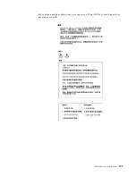
Para Conectar:
Para Desconectar:
1.
DESLIGUE Tudo.
2.
Primeiramente, conecte todos os cabos aos
dispositivos.
3.
Conecte os cabos de sinal aos conectores.
4.
Conecte os cabos de alimentação às tomadas.
5.
LIGUE os dispositivos.
1.
DESLIGUE Tudo.
2.
Primeiramente, remova os cabos de alimentação das
tomadas.
3.
Remova os cabos de sinal dos conectores.
4.
Remova todos os cabos dos dispositivos.
Summary of Contents for 86655RY - Netfinity 7600 - 8665
Page 1: ...IBM Hardware Maintenance Manual Netfinity 7600 Type 8665 Models 1RY 2RY ...
Page 2: ......
Page 3: ...IBM Hardware Maintenance Manual Netfinity 7600 Type 8665 Models 1RY 2RY ...
Page 10: ...viii Hardware Maintenance Manual Netfinity 7600 Type 8665 Models 1RY 2RY ...
Page 52: ...42 Hardware Maintenance Manual Netfinity 7600 Type 8665 Models 1RY 2RY ...
Page 104: ...94 Hardware Maintenance Manual Netfinity 7600 Type 8665 Models 1RY 2RY ...
Page 148: ...138 Hardware Maintenance Manual Netfinity 7600 Type 8665 Models 1RY 2RY ...
Page 252: ...242 Hardware Maintenance Manual Netfinity 7600 Type 8665 Models 1RY 2RY ...
Page 270: ...260 Hardware Maintenance Manual Netfinity 7600 Type 8665 Models 1RY 2RY ...
Page 271: ...Related service information 261 ...
Page 272: ...262 Hardware Maintenance Manual Netfinity 7600 Type 8665 Models 1RY 2RY ...
Page 273: ...Related service information 263 ...
Page 274: ...264 Hardware Maintenance Manual Netfinity 7600 Type 8665 Models 1RY 2RY ...
Page 284: ...274 Hardware Maintenance Manual Netfinity 7600 Type 8665 Models 1RY 2RY ...
Page 285: ...Related service information 275 ...
Page 292: ...282 Hardware Maintenance Manual Netfinity 7600 Type 8665 Models 1RY 2RY ...
Page 293: ......