


Installing options
81
5.
If you disconnected any cables from the back of the server, reconnect the cables;
then, plug the power cords into properly grounded electrical outlets.
Note:
If necessary, see “Cabling the server” on page 93 for connector locations.
Reconfiguring the server
When you start the server for the first time after you add or remove an internal option
or an external SCSI device, you might see a message telling you that the configuration
has changed. Run the Configuration/Setup Utility program to save the new
configuration information. See “Chapter . Configuring the server,” on page 43.
Some options have device drivers that you need to install. Refer to the documentation
that comes with the option for information about installing any required device
drivers.
If you have installed a new microprocessor, you might want to upgrade the operating
system to support symmetric multiprocessing (SMP).
Run the Configuration/Setup Utility program to save the new configuration
information. See “Chapter . Configuring the server,” on page 43.
If you have installed or removed a hard disk drive, refer to “Chapter . Installing and
configuring ServeRAID controllers,” on page 139 for information about reconfiguring
the disk arrays.
Connecting external options
Review the information in “Before you begin” on page 60. Also, read the
documentation that comes with the options.
To attach an external device:
1.
Turn off the server and all attached devices.
2.
Follow the instructions that come with the option to prepare it for installation and
to connect it to the server.
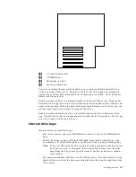
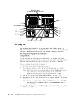
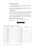
Input/output ports
This section provides information about the input/output (I/O) ports on the rear of
the server. These ports include the following:
•
One parallel port
•
One video port
•
One keyboard port
•
One auxiliary-device port (mouse)
•
One dual-channel Ultra-2 SCSI port
•
Two serial ports
•
Two Universal Serial bus (USB) ports
•
One Ethernet port
•
Three communication ports dedicated to the Netfinity Advanced System
Management processor
Refer to the following illustration for the location of input and output connectors.
Summary of Contents for 86655RY - Netfinity 7600 - 8665
Page 1: ...IBM Hardware Maintenance Manual Netfinity 7600 Type 8665 Models 1RY 2RY ...
Page 2: ......
Page 3: ...IBM Hardware Maintenance Manual Netfinity 7600 Type 8665 Models 1RY 2RY ...
Page 10: ...viii Hardware Maintenance Manual Netfinity 7600 Type 8665 Models 1RY 2RY ...
Page 52: ...42 Hardware Maintenance Manual Netfinity 7600 Type 8665 Models 1RY 2RY ...
Page 104: ...94 Hardware Maintenance Manual Netfinity 7600 Type 8665 Models 1RY 2RY ...
Page 148: ...138 Hardware Maintenance Manual Netfinity 7600 Type 8665 Models 1RY 2RY ...
Page 252: ...242 Hardware Maintenance Manual Netfinity 7600 Type 8665 Models 1RY 2RY ...
Page 270: ...260 Hardware Maintenance Manual Netfinity 7600 Type 8665 Models 1RY 2RY ...
Page 271: ...Related service information 261 ...
Page 272: ...262 Hardware Maintenance Manual Netfinity 7600 Type 8665 Models 1RY 2RY ...
Page 273: ...Related service information 263 ...
Page 274: ...264 Hardware Maintenance Manual Netfinity 7600 Type 8665 Models 1RY 2RY ...
Page 284: ...274 Hardware Maintenance Manual Netfinity 7600 Type 8665 Models 1RY 2RY ...
Page 285: ...Related service information 275 ...
Page 292: ...282 Hardware Maintenance Manual Netfinity 7600 Type 8665 Models 1RY 2RY ...
Page 293: ......


