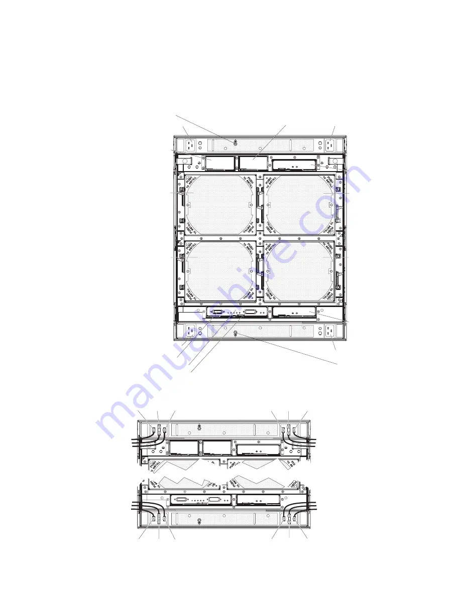
Rear
view
This
section
identifies
the
components,
connectors,
and
LEDs
on
the
rear
of
the
BladeCenter
HT
unit.
The
following
illustration
shows
a
BladeCenter
HT
Type
8750
with
ac-power
connectors.
Power connector 3
Power connector 1
Power connector 2
Power connector 4
Network-clock
bay 1
Network-clock
bay 2
Multiplexer expansion
module 1
Multiplexer expansion
module 2
Fan module 1
Fan module 3
Fan module 2
Fan module 4
Serial connector
Alarm panel module
Telco alarm connector
ESD connector
ESD connector
The
following
illustration
shows
a
BladeCenter
HT
Type
8740
with
dc-power
connections.
RTN
GND -48v
RTN
GND
-48v
RTN
GND
-48v
RTN
GND -48v
Chapter
2.
BladeCenter
HT
unit
power,
components,
and
indicators
21
Summary of Contents for 87401RU
Page 3: ...BladeCenter HT Type 8740 and 8750 Installation and User s Guide...
Page 8: ...vi BladeCenter HT Type 8740 and 8750 Installation and User s Guide...
Page 82: ...66 BladeCenter HT Type 8740 and 8750 Installation and User s Guide...
Page 92: ...76 BladeCenter HT Type 8740 and 8750 Installation and User s Guide...
Page 108: ...92 BladeCenter HT Type 8740 and 8750 Installation and User s Guide...
Page 109: ......
Page 110: ...Part Number 44R5188 Printed in USA 1P P N 44R5188...


