Note:
After
ac
power
has
been
removed
from
the
server,
power
remains
available
to
the
LEDs
for
up
to
12
hours,
after
which
time
you
must
turn
on
the
server
to
supply
power
to
the
LEDs.
1)
Read
Appendix
B,
“Safety
information,”
on
page
129
and
“Installation
guidelines”
on
page
15.
2)
Turn
off
the
server
and
all
attached
peripheral
devices.
3)
Disconnect
all
power
cords
and
external
cables
from
the
back
of
the
server.
4)
Remove
the
server
cover
(see
“Removing
the
cover”
on
page
18).
5)
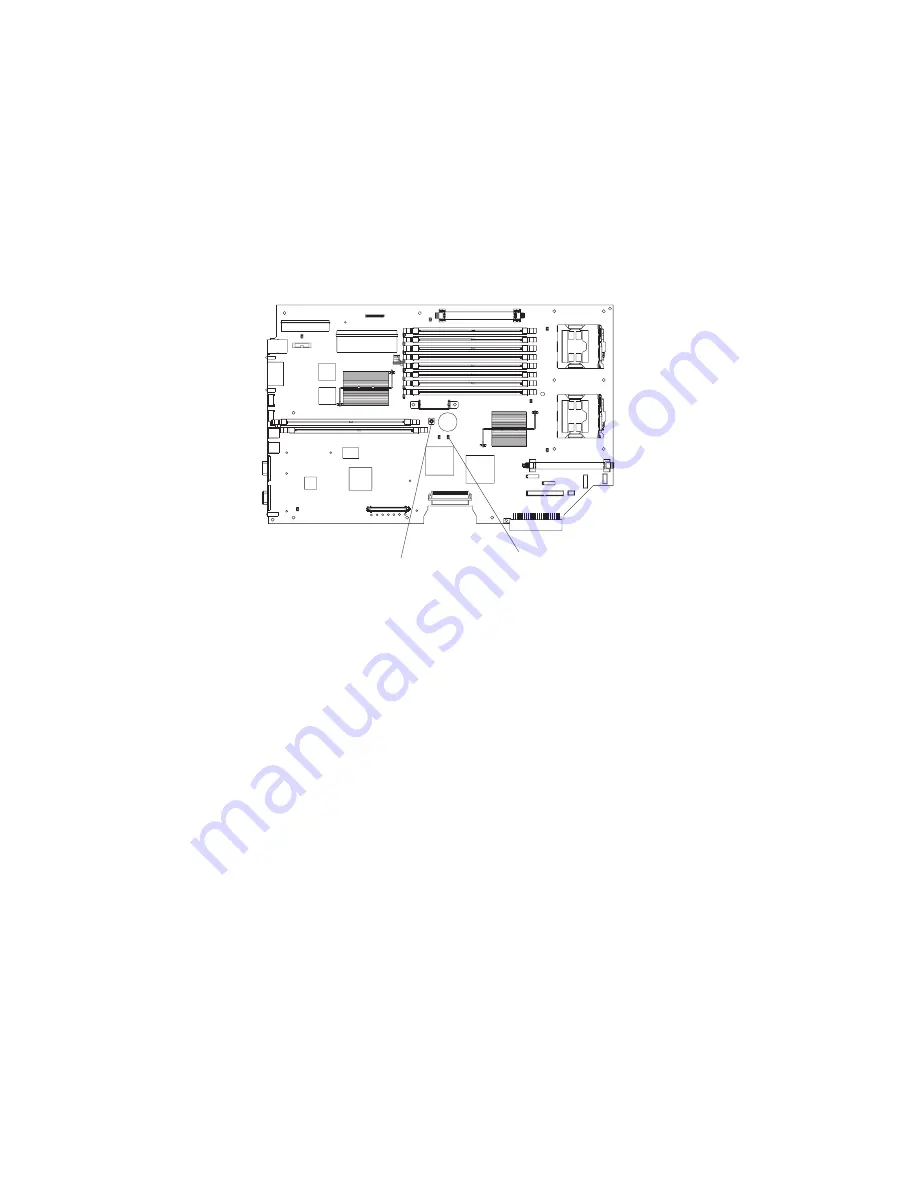
Press
and
hold
the
blue
light
path
diagnostic
button
(see
Figure
63)
to
illuminate
the
system
board
LEDs.
Important:
You
can
press
this
button
for
no
longer
than
two
minutes
to
light
the
LEDs.
After
this
time,
the
power
to
the
LEDs
is
exhausted.
Note:
If
no
LEDs
are
lit
when
you
press
the
light
path
diagnostic
button,
check
the
light
path
activity
LED;
if
the
light
path
activity
LED
lights
while
you
are
pressing
the
light
path
diagnostic
button,
this
indicates
that
the
light
path
is
working
properly
and
that
there
are
no
LEDs
lit
with
this
particular
error.
c.
If
the
lit
LED
on
the
light
path
diagnostics
panel
does
not
refer
to
a
specific
internal
component,
continue
with
step
5.
5.
Go
to
the
table
at
“Light
path
diagnostics
errors”
on
page
93
and
find
the
entry
for
the
associated
lit
LED;
then,
replace
the
indicated
component
or
take
the
indicated
action.
Notes:
v
The
system-error
log
and
the
BMC
log
might
contain
additional
information
that
will
be
helpful
before
replacing
a
component.
v
If
an
LED
on
the
light
path
diagnostics
panel
is
lit
and
the
system-error
LED
is
not
lit,
there
is
probably
an
LED
problem.
Run
LED
diagnostics
(see
“Starting
the
diagnostic
programs”
on
page
71).
Light Path
activity LED (CR 60)
Light Path diagnostic
button (SW 2)
Figure
63.
Lighting
the
light
path
LEDs
without
ac
power
Chapter
5.
Diagnostics
75
Summary of Contents for 88371RU
Page 1: ...xSeries 336 Type 1879 and Type 8837 Hardware Maintenance Manual and Troubleshooting Guide...
Page 2: ......
Page 3: ...xSeries 336 Type 1879 and Type 8837 Hardware Maintenance Manual and Troubleshooting Guide...
Page 15: ...Server on off 8 to 80 Shipment 5 to 100 Chapter 1 General information 5...
Page 22: ...12 xSeries 336 Type 1879 and Type 8837 Hardware Maintenance Manual and Troubleshooting Guide...
Page 24: ...14 xSeries 336 Type 1879 and Type 8837 Hardware Maintenance Manual and Troubleshooting Guide...
Page 92: ...82 xSeries 336 Type 1879 and Type 8837 Hardware Maintenance Manual and Troubleshooting Guide...
Page 149: ...Appendix B Safety information 139...
Page 150: ...140 xSeries 336 Type 1879 and Type 8837 Hardware Maintenance Manual and Troubleshooting Guide...
Page 151: ...Appendix B Safety information 141...
Page 152: ...142 xSeries 336 Type 1879 and Type 8837 Hardware Maintenance Manual and Troubleshooting Guide...
Page 153: ...Appendix B Safety information 143...
Page 154: ...144 xSeries 336 Type 1879 and Type 8837 Hardware Maintenance Manual and Troubleshooting Guide...
Page 155: ...Appendix B Safety information 145...
Page 165: ...Appendix B Safety information 155...
Page 166: ...156 xSeries 336 Type 1879 and Type 8837 Hardware Maintenance Manual and Troubleshooting Guide...
Page 167: ...Appendix B Safety information 157...
Page 168: ...158 xSeries 336 Type 1879 and Type 8837 Hardware Maintenance Manual and Troubleshooting Guide...
Page 172: ...162 xSeries 336 Type 1879 and Type 8837 Hardware Maintenance Manual and Troubleshooting Guide...
Page 185: ......
Page 186: ...Part Number 25K8109 1P P N 25K8109...


