Note:
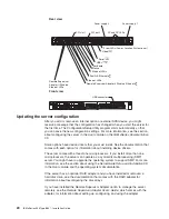
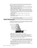
Hard
disk
drive
activity
for
the
SCSI
drives
is
shown
in
two
places,
on
the
hard
disk
drive
itself
and
also
on
the
hard
disk
drive
activity
LED
on
the
operator
information
panel.
There
is
no
hard
disk
drive
activity
LED
for
the
SATA
drive.
The
only
place
the
SATA
drive
indicates
hard
disk
drive
activity
is
on
the
operator
information
panel.
v
Location
Led:
Use
this
blue
LED
to
visually
locate
the
server
if
it
is
in
a
location
with
numerous
other
servers.
You
can
use
IBM
Director
to
light
this
LED
remotely.
This
LED
is
controlled
by
the
BMC.
v
Information
LED:
When
this
amber
LED
is
lit,
it
indicates
that
a
non-critical
event
has
occurred.
Check
the
error
log
for
additional
information.
See
the
note
in
the
Light
Path
diagnostics
LEDs
section
for
more
information
about
error
logs.
v
System-error
LED:
When
this
amber
LED
is
lit,
it
indicates
that
a
system
error
has
occurred.
A
System-error
LED
is
also
on
the
rear
of
the
server.
An
LED
on
the
Light
Path
diagnostics
panel
on
the
system
board
is
also
lit
to
help
isolate
the
error.
This
LED
is
controlled
by
the
BMC.
v
Release
Latch:
Press
the
release
latch,
on
the
right
side
of
the
operator
information
panel,
to
slide
out
the
operator
information
panel
and
view
the
Light
Path
LEDs
and
buttons.
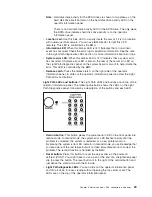
Light
Path
LEDs
and
buttons:
The
Light
Path
LEDs
and
buttons
are
on
top
of
the
operator
information
panel.
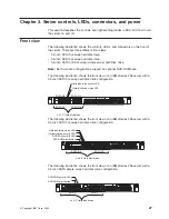
The
following
illustration
shows
the
LEDs
on
the
Light
Path
Diagnostics
panel,
followed
by
a
description
of
the
buttons
and
each
LED.
v
Remind
button:
This
button
places
the
system-error
LED
on
the
front
panel
into
remind
mode.
In
remind
mode,
the
system
error
LED
flashes
rapidly
until
the
problem
is
corrected,
the
system
is
restarted,
or
a
new
problem
occurs.
By
placing
the
system
error
LED
indicator
in
remind
mode,
you
acknowledge
that
you
are
aware
of
the
last
failure
but
will
not
take
immediate
action
to
correct
the
problem.
The
remind
function
is
handled
by
the
BMC.
v
Reset
button:
Press
this
button
to
reset
the
server
and
run
the
power-on
self-test
(POST).
You
might
have
to
use
a
pen
or
the
end
of
a
straightened
paper
clip
to
press
the
button.
The
reset
button
is
to
the
right
of
the
remind
button
and
just
above
the
small
circle
with
the
R
inside.
v
Light
Path
diagnostic
LEDs:
You
can
slide
out
the
operator
information
panel
and
drop
it
down
for
easy
viewing
without
opening
the
top
server
cover.
The
LEDs
are
on
the
top
of
the
operator
information
panel.
Chapter
3.
Server
controls,
LEDs,
connectors,
and
power
29
Summary of Contents for 883725U
Page 3: ...IBM xSeries 336 Type 8837 Installation Guide ERserver...
Page 18: ...6 IBM xSeries 336 Type 8837 Installation Guide...
Page 38: ...26 IBM xSeries 336 Type 8837 Installation Guide...
Page 46: ...34 IBM xSeries 336 Type 8837 Installation Guide...
Page 64: ...52 IBM xSeries 336 Type 8837 Installation Guide...
Page 66: ...54 IBM xSeries 336 Type 8837 Installation Guide...
Page 112: ...100 IBM xSeries 336 Type 8837 Installation Guide...
Page 113: ......
Page 114: ...Part Number 25R4613 Printed in USA 1P P N 25R4613...

