background image

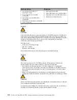
Instrução


2


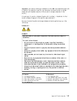
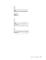
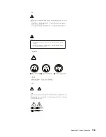
CUIDADO:


Ao


substituir


a


bateria


de


lítio,


utilize


apenas


uma


bateria


IBM,


Número


de


Peça


33F8354


ou


uma


bateria


de


tipo


equivalente,


recomendada


pelo


fabricante.


Se


o


seu


sistema


possui


um


móídulo


com


uma


bateria


de


lítio,


substitua-o


apenas


pelo


mesmo


tipo


de


mídulo,


do


mesmo


fabricante.


A


bateria


contém


lítio


e


pode


explodir


se


não


for


utilizada,


manuseada


e


descartada


de


maneira


correta.


Não:


v


Jogue


ou


coloque


na


água


v


Aqueça


a


mais


de


100°C


(212°F)


v


Conserte


nem


desmonte

Para


descartar


a


bateria,


entre


em


contato


com


a


área


de


atendimento


a


clientes


IBM,


pelo


telefone


(011)


889-8986,


para


obter


informações


sobre


como


enviar


a


bateria


pelo


correio


para


a


IBM.


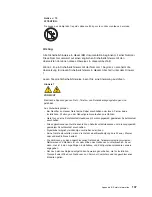
Instrução


3


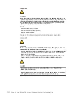
PRECAUCIÓN:


Quando


produtos


a


laser


(unidades


de


CD-ROM,


unidades


de


DVD,


dispositivos


de


fibra


ítica,


transmissores,


etc.)


estiverem


instalados,


observe


o


seguinte:


v


Não


remova


as


tampas.


A


remoção


das


tampas


de


um


produto


a


laser


pode


resultar


em


exposição


prejudicial


à


radiação


de


laser.


Nenhuma


peça


localizada


no


interior


do


dispositivo


pode


ser


consertada.


v


A


utilização


de


controles


ou


ajustes


ou


a


execução


de


procedimentos


diferentes


dos


especificados


aqui


pode


resultar


em


exposição


prejudicial


à


radiação.


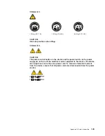
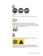
PERIGO


Alguns


produtos


a


laser


contêm


um


diodo


laser


da


Classe


3A


ou


Classe


3B


embutido.


Observe


o


seguinte:


Radiação


de


laser


quando


aberto.


Não


olhe


diretamente


para


o


raio


a


olho


nu


ou


com


instrumentos


íticos,


e


evite


exposição


direta


ao


raio.


126


xSeries


346


Types


8840


and


1880:


Hardware


Maintenance


Manual


and


Troubleshooting


Guide

Summary of Contents for 884015U

Page 1: ...xSeries 346 Types 8840 and 1880 Hardware Maintenance Manual and Troubleshooting Guide...

Page 2: ......

Page 3: ...xSeries 346 Types 8840 and 1880 Hardware Maintenance Manual and Troubleshooting Guide...

Page 4: ...mation in Appendix B Safety information on page 117 13th Edition February 2008 Copyright International Business Machines Corporation 2005 2007 All rights reserved US Government Users Restricted Rights...

Page 5: ...adapters 18 Installing a hot swap drive 26 Installing memory modules 27 Installing a microprocessor 30 Installing a hot swap power supply 35 Replacing a hot swap fan 37 Replacing the battery 38 Compl...

Page 6: ...out 69 Troubleshooting the Ethernet controller 70 Network connection problems 70 Ethernet controller troubleshooting chart 71 Ethernet controller messages 71 Chapter 6 Symptom to FRU index 73 Beep sym...

Page 7: ...Safety information 117 General safety 117 Electrical safety 118 Safety inspection guide 119 Handling electrostatic discharge sensitive devices 120 Grounding requirements 120 Safety notices multilingu...

Page 8: ...vi xSeries 346 Types 8840 and 1880 Hardware Maintenance Manual and Troubleshooting Guide...

Page 9: ...er avant de proc der aux op rations d crites par les instructions Lesen Sie alle Sicherheitshinweise bevor Sie eine Anweisung ausf hren Accertarsi di leggere tutti gli avvisi di attenzione e di perico...

Page 10: ...upport You can download the most current diagnostic BIOS flash and device driver files from http www ibm com support viii xSeries 346 Types 8840 and 1880 Hardware Maintenance Manual and Troubleshootin...

Page 11: ...ve the problem yourself or to provide helpful information to a service technician In addition to this Hardware Maintenance Manual and Troubleshooting Guide the following xSeries 346 Types 8840 and 188...

Page 12: ...ation or advice that might help you avoid inconvenient or problem situations v Attention These notices indicate possible damage to programs devices or data An attention notice is placed just before th...

Page 13: ...one internal Ultra320 SCSI port dual channel controller with integrated RAID v Three Universal Serial Bus USB v1 1 ports Note The baseboard management controller is also known as the service processo...

Page 14: ...indicates that the drive has failed If an optional IBM ServeRAID controller is installed in the server when this LED is flashing slowly one flash per second it indicates that the drive is being rebui...

Page 15: ...no electrical power in the server The LED might be burned out To remove all electrical power from the server you must disconnect the power cord from the electrical outlet v USB connector Connect a US...

Page 16: ...s connector ASM connectors Use either of these connectors to connect the server to an Integrated xSeries Adapter IXA that is installed in the server System locator LED Use this LED to visually locate...

Page 17: ...operating systems require an orderly shutdown before you turn off the server See your operating system documentation for information about shutting down the operating system Statement 5 CAUTION The po...

Page 18: ...8 xSeries 346 Types 8840 and 1880 Hardware Maintenance Manual and Troubleshooting Guide...

Page 19: ...the installation of your server to configure basic hardware features such as an integrated SCSI controller with RAID capabilities and to simplify the installation of your operating system v SCSISelec...

Page 20: ...ars press F1 If you have set both a power on password and an administrator password you must type the administrator password to access the full Configuration Setup Utility menu If you do not type the...

Page 21: ...connectors 44 SCSI cabling requirements 45 SCSI IDs 45 SCSI connector 45 Universal Serial Bus version 1 1 or 2 0 connectors 46 Video connector 46 This chapter provides detailed instructions for instal...

Page 22: ...ling and airflow replace the server cover before turning on the server Operating the server for extended periods of time more than 30 minutes with the server cover removed might damage server componen...

Page 23: ...not touch solder joints pins or exposed printed circuitry v Do not leave the device where others can handle and damage it v While the device is still in its static protective package touch it to an un...

Page 24: ...can be hot swapped which means that if the server and operating system support hot swap capability you can remove or install the component while the server is running Orange can also indicate touch p...

Page 25: ...t might differ slightly from your hardware Air baffle Microprocessor baffle Memory module System board Filler panel for drive bay PCI riser card cage PCI low profile card cage VRM Heat sink Microproce...

Page 26: ...and power cords see Turning off the server on page 7 3 Press down on the left and right side latches and pull the server out of the rack enclosure until both slide rails lock Note You can reach the c...

Page 27: ...d Installation guidelines on page 11 2 Turn off the server and peripheral devices and disconnect all power cords and external cables see Turning off the server on page 7 then remove the cover see Remo...

Page 28: ...00 MHz Non hot plug 64 bit PCI X slot 3 PCI bus B 133 MHz Non hot plug 64 bit PCI X slot 4 PCI bus C 133 MHz v The system scans devices in the following order if you have not changed the default boot...

Page 29: ...ntly The following illustration shows how to install the ServeRAID 7k ServerRAID 7k Connector Note If there is a gap between the card and the retaining clips the card has not been properly installed I...

Page 30: ...11 2 Turn off the server and peripheral devices and disconnect all power cords and external cables see Turning off the server on page 7 then remove the cover see Removing the cover on page 16 3 Deter...

Page 31: ...an adapter in PCI slot 3 or 4 remove the PCI riser card cage PCI riser card cage Retention latch 5 Slide the expansion slot cover out of the PCI low profile card cage or PCI riser card cage Chapter 3...

Page 32: ...ll the adapter The following illustration shows how to install an adapter in the PCI low profile card cage PCI adapter 22 xSeries 346 Types 8840 and 1880 Hardware Maintenance Manual and Troubleshootin...

Page 33: ...an adapter in the PCI riser card cage PCI adapter 7 If you removed the PCI low profile card cage to install the adapter press the PCI low profile card cage firmly into the connector until the retenti...

Page 34: ...d cage to install the adapter press the PCI riser card cage firmly into the connector and close the latch PCI riser card cage Retention latch 8 Connect any needed cables to the adapter 24 xSeries 346...

Page 35: ...ng for an adapter installed in the PCI low profile card cage Note Remove the PCI riser card cage the PCI low profile card cage and the fan bracket before you route the cables Reinstall the components...

Page 36: ...e server supports and other information that you must consider when installing a hard disk drive v The server supports six 1 inch 26 mm slim 3 5 inch low voltage differential LVD hard disk drives inst...

Page 37: ...lit continuously that drive is faulty and must be replaced If the green hard disk drive activity LED is flashing the drive is being accessed Note If you have a RAID configuration using the integrated...

Page 38: ...7 and 8 v The server supports online spare memory This feature disables the failed memory from the system configuration and activates an online spare memory pair of DIMMs to replace the failed active...

Page 39: ...on page 11 and the safety information beginning on page Appendix B Safety information on page 117 2 Turn off the server and disconnect all power cords and external cables see Turning off the server o...

Page 40: ...btain an SMP capable operating system For a list of supported operating systems and other options go to http www ibm com servers eserver serverproven compat us v To order additional microprocessor opt...

Page 41: ...of the microprocessor connector locations and other microprocessor related components on the system board Microprocessor 1 J22 Microprocessor 2 J23 VRM J72 Note For additional illustrations of the sys...

Page 42: ...B Safety information on page 117 2 Turn off the server and disconnect all power cords and external cables see Turning off the server on page 7 then remove the server cover see Removing the cover on p...

Page 43: ...roprocessor socket and system board c Rotate the locking lever on the microprocessor socket from its closed and locked position until it stops or clicks in the fully open position approximately 135 an...

Page 44: ...Do not touch the thermal grease on the bottom of the heat sink or set down the heat sink Touching the thermal grease will contaminate it For details see the information about thermal grease on page 3...

Page 45: ...o now Otherwise go to Completing the installation on page 39 Installing a hot swap power supply The server supports a maximum of two hot swap power supplies Statement 8 CAUTION Never remove the cover...

Page 46: ...tion During normal operation each power supply bay must have either a power supply or power supply blank installed for proper cooling 3 Install the power supply in the bay a Move the handle on the pow...

Page 47: ...shows the locations of the hot swap fans Fan 9 Fan 3 Fan 4 Fan 5 Fan 6 Fan 1 Fan 2 Fan 10 Fan 11 Fan 12 Fan 7 Fan 8 Optional Complete the following steps to replace a hot swap fan 1 Read the Installa...

Page 48: ...S and Canada call your IBM reseller or IBM marketing representative Note After you replace the battery you must reconfigure the server and reset the system date and time Statement 2 CAUTION When repla...

Page 49: ...til it snaps into place 9 Reconnect the internal cables that you disconnected 10 Connect all external cables and all power cords 11 Reinstall the air baffle 12 Reinstall the server cover see Completin...

Page 50: ...nimum depth of 70 mm 2 76 in between the front mounting flange and the inside of the front door Minimum depth of 157 mm 6 18 in between the rear mounting flange and the inside of the rear door Minimum...

Page 51: ...ration When you start the server for the first time after you add or remove an internal option or external SCSI device you might receive a message that the configuration has changed The Configuration...

Page 52: ...ou can attach additional external options to the other input output I O connectors on the front and rear of the server See Input output connectors on page 43 for more information Complete the followin...

Page 53: ...cations of these connectors Rear view TX RX TX RX LINK LINK Ethernet 2 Ethernet 1 Mouse Universal Serial Bus USB Serial Video Keyboard Remote Supervisor Adapter II Ethernet SlimLine ASM SCSI System lo...

Page 54: ...er to an Integrated xSeries Adapter IXA that is installed in the server Keyboard connector Use this connector to connect a PS 2 non USB keyboard to the server The following illustration shows a keyboa...

Page 55: ...y SCSI IDs Each SCSI device that is connected to a SCSI controller must have a unique SCSI ID This ID enables the SCSI controller to identify the device and ensure that different devices on the same S...

Page 56: ...B devices than the server has USB connectors for use a USB hub to connect additional devices If you connect a PS 2 non USB keyboard to the keyboard connector USB ports and devices are disabled during...

Page 57: ...ing and replacing the thermal grease between the heat sink and the microprocessor Important If you are installing the heat sink on the same processor that it was removed from be sure that v The therma...

Page 58: ...ns for removing and replacing the fan bracket Note v Read Installation guidelines on page 11 v Read the safety notices at Appendix B Safety information on page 117 v Read Handling static sensitive dev...

Page 59: ...the following steps to remove the power cage assembly 1 Turn off the server and any attached devices 2 Disconnect external cables and option cables from the back of the server 3 Remove the server cove...

Page 60: ...mplete the following steps to remove the hard disk drive backplane 1 Turn off the server and any attached devices 2 Disconnect external cables and option cables from the back of the server 3 Remove th...

Page 61: ...the safety notices at Appendix B Safety information on page 117 v Read Handling static sensitive devices on page 13 Complete the following steps to remove the media cage 1 Turn off the server and any...

Page 62: ...r 1 Read the Installation guidelines on page 11 and the safety information beginning on page Appendix B Safety information on page 117 2 Turn off the server and disconnect all power cords and external...

Page 63: ...ase See Thermal grease on page 66 for instructions for removing and applying thermal grease Rotate the heat sink lever to the open position and carefully remove the heat sink 6 Rotate the locking leve...

Page 64: ...for user installable options DIMM 1 J1 DIMM 2 J2 DIMM 3 J3 DIMM 4 J4 DIMM 5 J5 DIMM 6 J6 DIMM 7 J7 DIMM 8 J8 Microprocessor 1 J22 Microprocessor 2 J23 Battery BH1 VRM J72 Remote Supervisor Adapter II...

Page 65: ...or panel J75 Media power J63 Diskette signal J39 IDE J67 Internal SCSI J25 Power backplane J41 System board external connectors The following illustration shows the external input output connectors on...

Page 66: ...Power on password override Changing the position of this switch bypasses the power on password check the next time the server is turned on and starts the Configuration Setup Utility program so that yo...

Page 67: ...r LED CR55 DIMM 4 error LED CR56 DIMM 5 error LED CR57 DIMM 6 error LED CR58 DIMM 7 error LED CR59 DIMM 8 error LED CR60 Microprocessor 1 error LED CR 61 Microprocessor 2 error LED CR 62 PCI riser car...

Page 68: ...Remove the cover see Removing the cover on page 16 4 Remove the air baffle see Removing the air baffle on page 17 5 Remove the fan bracket see Fan bracket on page 48 6 Disconnect and remove the PCI lo...

Page 69: ...inue with the next step 12 Remove the eight screws that secure the system board to the shuttle at the microprocessor retention modules Heat sink retention module screws 8 13 Remove the four standoff s...

Page 70: ...ement system board looking from the front of the server slide the shuttle under the retention tab on the right side of the chassis Be sure the alignment pin on the chassis shuttle is aligned with the...

Page 71: ...d hard disk drive cluster two or more servers sharing external storage devices If you suspect that it is part of a cluster you can run all diagnostic programs except the ones that test the storage uni...

Page 72: ...stem recorded an error see Chapter 6 Symptom to FRU index on page 73 11 Start the diagnostic programs 12 Check for the following responses v One beep v Readable instructions or the main menu 003 DID Y...

Page 73: ...continue 2 A single problem might cause several error messages When this occurs work to correct the cause of the first error message After you correct the cause of the first error message the other e...

Page 74: ...he NOS If the NOS is supported either there is no logical drive defined SCSI RAID systems or the ServerGuide System Partition is not present Run the ServerGuide program and ensure that setup is comple...

Page 75: ...g tested test_specific_string is an error code or other information about the error Starting the diagnostic programs Complete the following steps to start the diagnostic programs 1 Turn on the server...

Page 76: ...or to the hard disk The test log data is maintained only while the diagnostic programs are active When you exit from the diagnostic programs the test log is cleared saved test logs are not affected To...

Page 77: ...wer LEDs DC power green LED AC power green LED For more information about power supply LEDs see Power supply LED errors on page 100 Light path diagnostics Use light path diagnostics to diagnose system...

Page 78: ...tics LEDs For a complete list of the LEDs on the light path diagnostics panel the problems they indicate and actions to solve the problems see Light path diagnostics LEDs on page 83 Recovering the BIO...

Page 79: ...from 0 to 7 and press Enter to accept your choice 11 Remove the BIOS recovery diskette from the diskette drive 12 Turn off the server and disconnect all power cords and external cables then remove th...

Page 80: ...tached at all connections If the cable is attached but the problem remains try a different cable If you set the Ethernet controller to operate at either 100 Mbps or 1000 Mbps you must use Category 5 o...

Page 81: ...ork v Make sure that you have installed the network device drivers v The network might be idle Try sending data from this server Data is incorrect or sporadic v Make sure that you are using Category 5...

Page 82: ...72 xSeries 346 Types 8840 and 1880 Hardware Maintenance Manual and Troubleshooting Guide...

Page 83: ...re related system shutdown 103 Hard disk drive checkout 104 Host built in self test BIST 104 Bus fault messages 104 Undetermined problems 104 Problem determination tips 105 This index supports xSeries...

Page 84: ...ocessor if installed 2 Microprocessor 3 System board 1 1 3 CMOS write read test failed 1 Battery 2 Clear CMOS see Recovering the BIOS code on page 68 3 System board 1 1 4 BIOS EEPROM checksum failed 1...

Page 85: ...see Recovering the BIOS code on page 68 3 System board 2 3 1 Screen initialization failed System board 2 3 2 Screen memory failed System board 2 3 3 Screen retrace failed System board 2 3 4 Search fo...

Page 86: ...he configuration has changed 1 Run Diagnostics 2 Run the Configuration Setup Utility program Three short beeps 1 Reseat the DIMMs 2 Locate the failing DIMMs a Remove all DIMMs from the server b Beginn...

Page 87: ...order shown restarting the server each time v Trained service technician only Microprocessor 1 v Trained service technician only Microprocessor 2 if installed v Trained service technician only System...

Page 88: ...res using the default configuration 1 Run the Configuration Setup Utility program 2 Battery 3 System board 4 Microprocessor 101 102 System and processor error System board 106 System and processor err...

Page 89: ...onfiguration Setup Utility program 2 System board 186 Security hardware control logic failed 1 Run the Configuration Setup Utility program 2 System board 187 VPD serial number not set 1 Set serial num...

Page 90: ...ration error 1 Run the Configuration Setup Utility program 2 Battery 3 Microprocessor 962 Parallel port error 1 Disconnect the external cable on the parallel port 2 Run the Configuration Setup Utility...

Page 91: ...stem board 1602 Optional service processor not properly installed Disconnect all server and option power cords from server wait 30 seconds reconnect and retry 1762 Hard disk configuration error 1 Hard...

Page 92: ...that are not available 1 Reorder the adapters in the PCI slots It is important that your startup device is positioned early in the startup device order so that it is run by POST 2 Ensure that the PCI...

Page 93: ...zes clock speeds and clock frequencies 2 Microprocessor 2 01298101 Bad update data for microprocessor 1 1 Ensure all microprocessors have the same cache sizes clock speeds and clock frequencies 2 Micr...

Page 94: ...ocessor internal and external clock frequencies must be identical If the problem remains replace the system board VRM When the LED is lit an error occurred on the microprocessor voltage regulator modu...

Page 95: ...on the IBM xSeries Documentation CD for temperature information v Make sure that the air vents are not blocked BRD An error has occurred on the system board v Check the LEDs on the system board to id...

Page 96: ...oard damaged System board 015 XXX 015 Failed USB external loopback test 1 Make sure the parallel port is not disabled 2 Run the USB external loopback test again 3 System board 015 XXX 198 USB device c...

Page 97: ...d optional microprocessor test 1 VRM 2 for optional microprocessor 2 2 Optional microprocessor 2 166 051 000 System Management Failed Unable to communicate with RSA It may be busy Run the test again 1...

Page 98: ...tem board 1 Remote Supervisor Adapter II SlimLine 2 System board 166 260 000 System Management Failed Restart RSA error After restarting RSA communication was lost Unplug and cold boot to reset RSA 1...

Page 99: ...420 1 Disconnect all server and option power cords from the server wait 30 seconds reconnect and retry 2 Reflash or update firmware for BMC 3 Power backplane 4 System board 166 414 001 System Manageme...

Page 100: ...M drive 4 System board 217 198 XXX Could not establish drive parameters 1 Check cable and termination 2 SCSI backplane 3 Hard disk 217 XXX 000 Failed BIOS hard disk test Note If RAID is configured the...

Page 101: ...XX 00N Failed Ethernet test on adapter in PCI slot n 1 Adapter in PCI slot n 2 System board 415 XXX 000 Failed Modem test 1 Cable Note Ensure modem is present and attached to server 2 Modem 3 System b...

Page 102: ...etermine which components should be replaced by a field service technician Symptom FRU action The diskette drive activity LED stays lit or the server bypasses the diskette drive or the diskette drive...

Page 103: ...ely to the rear of the server and attached options v When the server is turned on air is flowing from the rear of the server at the fan grill If there is no airflow the fan is not working This causes...

Page 104: ...a Start the Configuration Setup Utility program b Enable the DIMM c Save the configuration and restart the server 3 DIMM 4 System board Microprocessor error symptoms Note See System on page 108 to de...

Page 105: ...goes blank when you start some application programs 1 Verify that v The application program is not setting a display mode higher than the capability of the monitor v You installed the necessary device...

Page 106: ...ation information in the Configuration Setup Utility program Whenever memory or an option is changed you must update the configuration 2 Option you just installed An IBM option that used to work does...

Page 107: ...ot turn on v System board The server does not turn off 1 Verify whether you are using an ACPI or non ACPI operating system If you are using a non ACPI operating system a Press Ctrl Alt Delete b Turn o...

Page 108: ...ensure that only one drive is set as the primary drive Start the CD from the primary drive The SCSI RAID program cannot view all installed drives or the NOS cannot be installed v Verify that there ar...

Page 109: ...the software Note If you have just installed an adapter or memory you might have a memory address conflict v The software is designed to operate on the server v Other software works on the server v Th...

Page 110: ...h no errors a Power switch assembly b System board 2 Remove the adapters and disconnect the cables and power connectors to all internal and external devices Turn on the system If the dc good LED is li...

Page 111: ...ge 12 DASD under recommended temperature sensor x level warning direct access storage device bay x had under temperature condition Ambient temperature must be within normal operating specifications se...

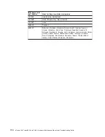
Page 112: ...nly Power supply x fan fault level critical fan fault in power supply x Replace power supply x Power supply x 12 V fault level critical overcurrent condition detected See Power checkout on page 69 Pow...

Page 113: ...board is over temperature 1 Ensure that the server is being properly cooled see System reliability guidelines on page 12 2 Replace board System shutoff due to CPU x over temperature level critical CPU...

Page 114: ...emote Supervisor Adapter and the Remote Supervisor Adapter connector on the PCI riser card 2 Memory DIMMs 3 System board Failure reading I2C device Check devices on bus 1 1 Reseat the cable between th...

Page 115: ...dule with a minimum of two 256 MB DIMMs 4 Turn on the server If the problem remains suspect the following FRUs in the order listed Power supply Power cage assembly System board Notes 1 If the problem...

Page 116: ...the same BIOS level v Have the same adapters attachments in the same locations v Have the same address jumpers terminators cabling v Have the same software versions and levels v Have the same diagnos...

Page 117: ...346 Types 8840 and 1880 To check for an updated parts listing on the Web complete the following steps 1 Go to http www ibm com support 2 Under Search technical support type 8872 or 8874 and click Sear...

Page 118: ...of the xSeries 346 Types 8840 and 1880 are shown in the following illustration 1 2 3 4 5 6 7 8 9 10 11 12 13 14 15 16 17 18 19 20 21 22 23 108 xSeries 346 Types 8840 and 1880 Hardware Maintenance Manu...

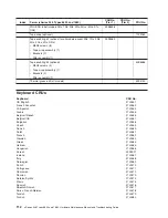
Page 119: ...mory 512MB ECC all models except 01x D1x DRx 13N1424 8 Memory 256 ECC DRR model 01x 90P1123 8 Memory 512MB 3200 ECC optional 73P2869 8 Memory 1GB 3200 ECC models D1x DRx 73P2870 8 Memory 1GB 3200 ECC...

Page 120: ...x 0Rx 39R7569 22 Microprocessor 3 0 GHz model 11x 90P1033 22 Microprocessor 3 0 GHz models 15x 17x 1Rx 13M8293 22 Microprocessor 3 2 GHz model 21x 90P1210 22 Microprocessor 3 2 GHz models 25x 2Rx 13M8...

Page 121: ...g Shuttle Latch 2 v Latch Low Profile PCI Retention 3 v Lid Low Profile PCI Retention 2 v Latch PCI Cage Retention 2 v Light Box Switch Card 1 v Latch Cable Strain Relief 2 v Holder FDD Wire Spring 2...

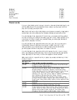
Page 122: ...dels 59P4740 Keyboard CRUs Keyboard CRU No US English 37L2551 French Canadian 37L2552 LA Spanish 37L2553 Arabic 37L2555 Belgium French 37L2556 Belgium UK 37L2557 Bulgarian 37L2558 Czech 37L2559 Danish...

Page 123: ...grounding type attachment plug The cord set should have the appropriate safety approvals for the country in which the equipment will be installed IBM power cords for a specific country or region are...

Page 124: ...da Bolivia Brazil Canada Cayman Islands Colombia Costa Rica Dominican Republic Ecuador El Salvador Guatemala Guyana Haiti Honduras Jamaica Japan Korea South Liberia Mexico Netherlands Antilles Nicarag...

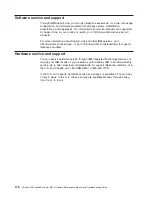
Page 125: ...grams come with information that contains troubleshooting procedures and explanations of error messages and error codes If you suspect a software problem see the information for the operating system o...

Page 126: ...http www ibm com planetwide for support telephone numbers Hardware service and support You can receive hardware service through IBM Integrated Technology Services or through your IBM reseller if your...

Page 127: ...start the machine ensure that other service representatives and the customer s personnel are not in a hazardous position v Place removed covers and other parts in a safe place away from all personnel...

Page 128: ...r cord If you cannot unplug it ask the customer to power off the wall box that supplies power to the machine and to lock the wall box in the off position v If you need to work on a machine that has ex...

Page 129: ...ction guide If any unsafe conditions are present you must determine how serious the apparent hazard could be and whether you can continue without first correcting the problem Consider these conditions...

Page 130: ...wearing a wrist strap v Use the black side of a grounded work mat to provide a static free work surface The mat is especially useful when handling ESD sensitive devices v Select a grounding system su...

Page 131: ...operly wired and grounded electrical outlet v Connect to properly wired outlets any equipment that will be attached to this product v When possible use one hand only to connect or disconnect signal ca...

Page 132: ...hen laser products such as CD ROMs DVD drives fiber optic devices or transmitters are installed note the following v Do not remove the covers Removing the covers of the laser product could result in e...

Page 133: ...l button on the device and the power switch on the power supply do not turn off the electrical current supplied to the device The device also might have more than one power cord To remove all electric...

Page 134: ...mounted devices 82 kg 180 lb Importante Todas as instru es de cuidado e perigo da IBM documentation come am com um n mero Este n mero utilizado para fazer refer ncia cruzada de uma instru o de cuidad...

Page 135: ...ncia de danos por fogo gua ou na estrutura v Desconecte cabos de alimenta o sistemas de telecomunica o redes e modems antes de abrir as tampas dos dispositivos a menos que especificado de maneira dif...

Page 136: ...eio para a IBM Instru o 3 PRECAUCI N Quando produtos a laser unidades de CD ROM unidades de DVD dispositivos de fibra tica transmissores etc estiverem instalados observe o seguinte v N o remova as tam...

Page 137: ...a do dispositivo assegure que todos os cabos de alimenta o estejam desconectados da fonte de energia el trica 1 2 Instru o 8 CUIDADO Nunca remova a tampa de uma fonte de alimenta o ou de qualquer pe a...

Page 138: ...tru o 10 CUIDADO N o coloque nenhum objeto com peso superior a 82 kg 180 lbs sobre dispositivos montados em rack 128 xSeries 346 Types 8840 and 1880 Hardware Maintenance Manual and Troubleshooting Gui...

Page 139: ...Appendix B Safety information 129...

Page 140: ...130 xSeries 346 Types 8840 and 1880 Hardware Maintenance Manual and Troubleshooting Guide...

Page 141: ...Appendix B Safety information 131...

Page 142: ...132 xSeries 346 Types 8840 and 1880 Hardware Maintenance Manual and Troubleshooting Guide...

Page 143: ...Appendix B Safety information 133...

Page 144: ...ours d un orage v Branchez tous les cordons d alimentation sur un socle de prise de courant correctement c bl et mis la terre v Branchez sur des socles de prise de courant correctement c bl s tout qui...

Page 145: ...utilisation v Ne la jetez pas l eau v Ne l exposez pas une temp rature sup rieure 100 C v Ne cherchez pas la r parer ou la d monter Pour la mise au rebut reportez vous la r glementation en vigueur Not...

Page 146: ...er totalement l unit du r seau lectrique d branchez tous les cordons d alimentation des socles de prise de courant 1 2 Notice n 8 ATTENTION N ouvrez jamais le bloc d alimentation ou tout l ment sur le...

Page 147: ...oder l sen Ferner keine Installations Wartungs oder Rekonfigurationsarbeiten durchf hren v Ger t nur an eine Schutzkontaktsteckdose mit ordnungsgem geerdetem Schutzkontakt anschlie en v Alle angeschlo...

Page 148: ...ren oder zerlegen Die rtlichen Bestimmungen f r die Entsorgung von Sonderm ll beachten Hinweis 3 ACHTUNG Wenn ein Laserprodukt z B CD ROM Laufwerke DVD Laufwerke Einheiten mit Glasfaserkabeln oder Tra...

Page 149: ...Servers auszuschalten mu sichergestellt werden da alle Netzkabel aus den Netzsteckdosen herausgezogen wurden 1 2 Hinweis 8 ACHTUNG Die Abdeckung oder eine Komponente eines Netzteils die wie nachfolge...

Page 150: ...onfrontare avvisi di attenzione o di pericolo in inglese con le versioni tradotte riportate in questa sezione Ad esempio se un avviso di attenzione inizia con il numero 1 la relativa versione tradotta...

Page 151: ...a di fuoco acqua o se sono presenti danni all apparecchiatura stessa v Scollegare i cavi di alimentazione i sistemi di telecomunicazioni le reti e i modem prima di aprire i coperchi delle unit se non...

Page 152: ...i Avviso 3 ATTENZIONE Quando si installano prodotti laser come ad esempio le unit DVD CD ROM a fibre ottiche o trasmettitori prestare attenzione a quanto segue v Non rimuovere i coperchi L apertura de...

Page 153: ...orrente elettrica dall unit accertarsi che tutti i cavi di alimentazione siano scollegati dalla sorgente di alimentazione 1 2 Avviso 8 ATTENZIONE Non togliere mai il coperchio di un alimentatore o qua...

Page 154: ...viso 10 ATTENZIONE Non poggiare oggetti che pesano pi di 82 kg sulla parte superiore delle unit montate in rack 144 xSeries 346 Types 8840 and 1880 Hardware Maintenance Manual and Troubleshooting Guid...

Page 155: ...Appendix B Safety information 145...

Page 156: ...146 xSeries 346 Types 8840 and 1880 Hardware Maintenance Manual and Troubleshooting Guide...

Page 157: ...Appendix B Safety information 147...

Page 158: ...148 xSeries 346 Types 8840 and 1880 Hardware Maintenance Manual and Troubleshooting Guide...

Page 159: ...en ingl s con las versiones traducidas que de dichas declaraciones pueden encontrarse en esta secci n Por ejemplo si una declaraci n de peligro empieza con el n mero 1 las traducciones de esta declara...

Page 160: ...bles de alimentaci n sistemas de telecomunicaciones redes y m dems conectados antes de abrir las cubiertas del dispositivo a menos que se indique lo contrario en los procedimientos de instalaci n y co...

Page 161: ...mento o la legislaci n local Declaraci n 3 PRECAUCI N Cuando instale productos l ser como por ejemplo CD ROM unidades DVD dispositivos de fibra ptica o transmisores tenga en cuenta las advertencias si...

Page 162: ...o aseg rese de desconectar todos los cables de alimentaci n de la fuente de alimentaci n 1 2 Declaraci n 8 PRECAUCI N No retire nunca la cubierta de una fuente de alimentaci n ni ninguna pieza que ten...

Page 163: ...Declaraci n 10 PRECAUCI N No coloque ning n objeto que pese m s de 82 kg 180 libras encima de los dispositivos montados en bastidor Appendix B Safety information 153...

Page 164: ...154 xSeries 346 Types 8840 and 1880 Hardware Maintenance Manual and Troubleshooting Guide...

Page 165: ...OF ANY KIND EITHER EXPRESS OR IMPLIED INCLUDING BUT NOT LIMITED TO THE IMPLIED WARRANTIES OF NON INFRINGEMENT MERCHANTABILITY OR FITNESS FOR A PARTICULAR PURPOSE Some states do not allow disclaimer of...

Page 166: ...the United States and other countries Java and all Java based trademarks and logos are trademarks or registered trademarks of Sun Microsystems Inc in the United States other countries or both Adaptec...

Page 167: ...recycling and disposal This unit contains materials such as circuit boards cables electromagnetic compatibility gaskets and connectors which may contain lead and copper beryllium alloys that require...

Page 168: ...changes or modifications to this equipment Unauthorized changes or modifications could void the user s authority to operate the equipment This device complies with Part 15 of the FCC Rules Operation i...

Page 169: ...s been tested and found to comply with the limits for Class A Information Technology Equipment according to CISPR 22 European Standard EN 55022 The limits for Class A equipment were derived for commer...

Page 170: ...160 xSeries 346 Types 8840 and 1880 Hardware Maintenance Manual and Troubleshooting Guide...

Page 171: ...etup and Installation CD 9 updating 41 Configuration Setup Utility program 9 configuring hardware 9 configuring your server 9 connectors 5 adapter 54 battery 54 cable 55 Ethernet 44 external port 55 i...

Page 172: ...ort 44 keyboard problems 93 L LEDs 5 diagnosing problems using 66 Ethernet activity 6 Ethernet link status 6 LEDs continued front view 4 power supply 67 rear view 5 system board 57 light path diagnost...

Page 173: ...6 serial port 97 software 99 R recovering the BIOS code 68 replacing battery 38 hot swap fan 37 reset button 68 S safety information electrical 7 SCSI adapter boot option 18 cable external devices 45...

Page 174: ...ctor 5 6 using Configuration Setup Utility 10 V video connector 6 video port 46 voltage regulator module installing 32 VRM See voltage regulator module W Web site BIOS flash diskette 68 compatible opt...

Page 175: ......

Page 176: ...Part Number 25K8115 Printed in USA 1P P N 25K8115...

Reviews: