


2.
For
additional
cabling
instructions,
see
the
User’s
Guide
on
the
IBM
xSeries
Documentation
CD
and
the
documentation
that
comes
with
the
options.
It
might
be
easier
for
you
to
route
any
cables
before
you
install
certain
options.
3.
Cable
identifiers
are
printed
on
the
cables
that
come
with
the
server
and
options.
Use
these
identifiers
to
connect
the
cables
to
the
correct
connectors.
For
example,
the
hard
disk
drive
cables
are
labeled
“HDD
option.”
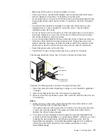
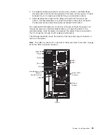
Two
cable-restraint
brackets
are
on
the
rear
of
the
server.
Route
the
power
cord
through
the
power-cord
restraint
bracket.
After
you
connect
the
cables
to
the
selected
devices,
route
the
cables
(for
example,
the
cables
that
are
connected
to
the
I/O
connectors)
through
the
I/O
cable-restraint
bracket.
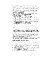
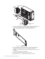
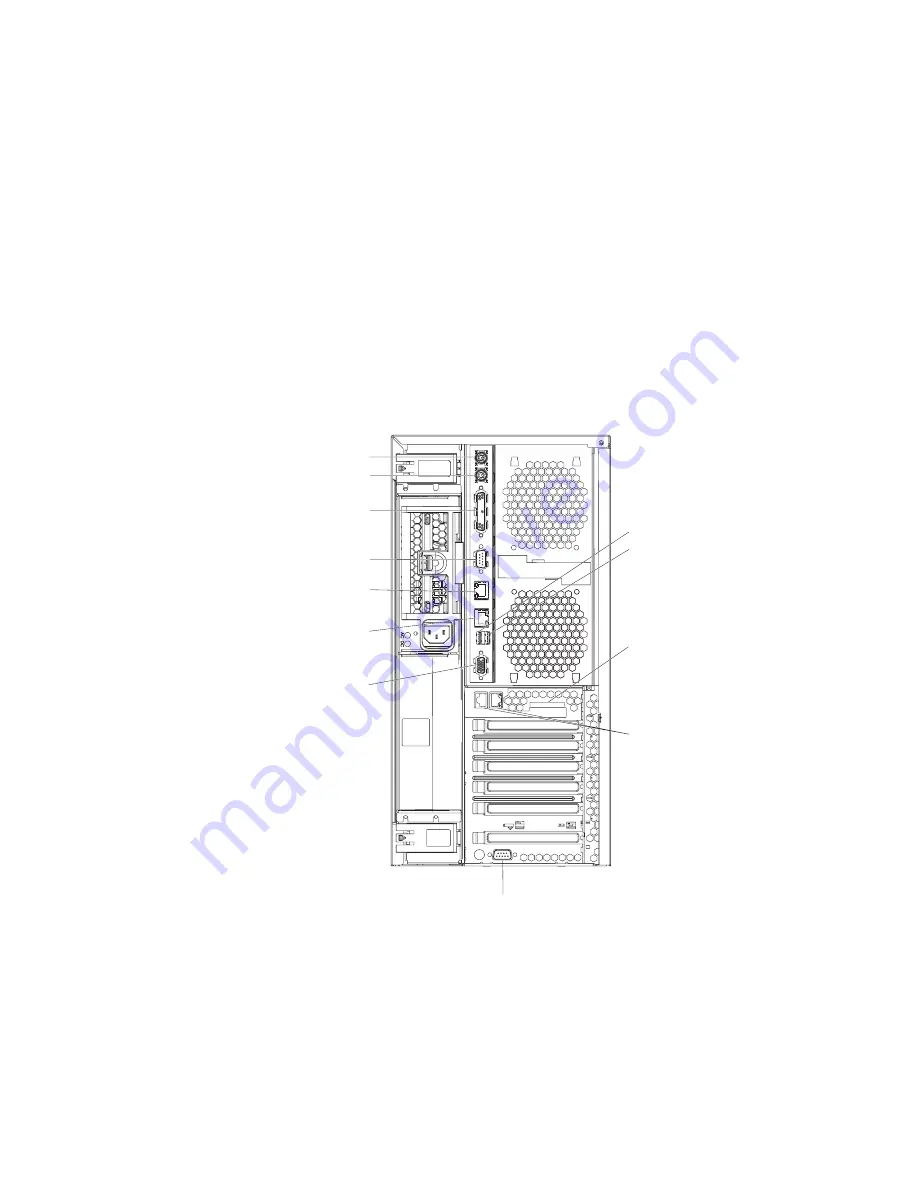
The
following
illustration
shows
the
location
of
the
input
and
output
connectors
on
the
rear
of
the
server.
Note:
The
USB
3
connector
is
on
the
front
of
the
server.
(See
“Front
view”
on
page
25
for
the
USB
3
connector
location.)
Keyboard
Mouse
Parallel
Serial 1
Serial 2
Ethernet
(System)
External SCSI
(Knockout)
USB 1
USB 2
ASM
Remote Supervisor
Adapter II
SlimLine Ethernet
Video
PO
WER SUPPL
Y
FILLER
REQ
UIRED FOR
SYSTEM COOLING
WITH EMPTY SLO
T
DO NO
T
THR
O
W
A
W
A
Y
A
TTENTION:
PO
WER SUPPL
Y
FILLER
REQ
UIRED FOR
SYSTEM COOLING
WITH EMPTY SLO
T
DO NO
T
THR
O
W
A
W
A
Y
A
TTENTION:
Chapter
2.
Installing
options
23
Summary of Contents for 8841 - eServer xSeries 236
Page 3: ...IBM xSeries 236 Type 8841 Installation Guide...
Page 7: ...Japanese Voluntary Control Council for Interference VCCI statement 80 Index 81 Contents v...
Page 8: ...vi IBM xSeries 236 Type 8841 Installation Guide...
Page 56: ...42 IBM xSeries 236 Type 8841 Installation Guide...
Page 98: ...84 IBM xSeries 236 Type 8841 Installation Guide...
Page 99: ......
Page 100: ...Part Number 31R1188 Printed in USA 1P P N 31R1188...


