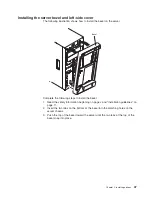


Installing
the
server
bezel
and
left-side
cover
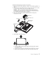
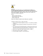
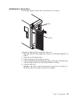
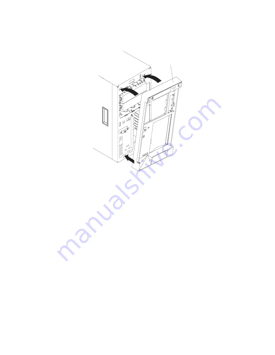
The
following
illustration
shows
how
to
install
the
bezel
on
the
server.
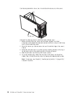
Bezel
Complete
the
following
steps
to
install
the
bezel:
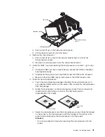
1.
Read
the
safety
information
beginning
on
page
v
and
“Installation
guidelines”
on
page
11.
2.
Insert
the
two
tabs
on
the
bottom
of
the
bezel
into
the
matching
holes
on
the
server
chassis.
3.
Push
the
top
of
the
bezel
toward
the
server
until
the
two
tabs
at
the
top
of
the
bezel
snap
into
place.
Chapter
2.
Installing
options
47
Summary of Contents for 8841 - eServer xSeries 236
Page 1: ...IBM xSeries 236 Type 8841 Option Installation Guide ERserver...
Page 2: ......
Page 3: ...IBM xSeries 236 Type 8841 Option Installation Guide ERserver...
Page 22: ...10 IBM xSeries 236 Type 8841 Option Installation Guide...
Page 64: ...52 IBM xSeries 236 Type 8841 Option Installation Guide...
Page 73: ......
Page 74: ...Part Number 31R1191 Printed in USA 1P P N 31R1191...