background image

Safety


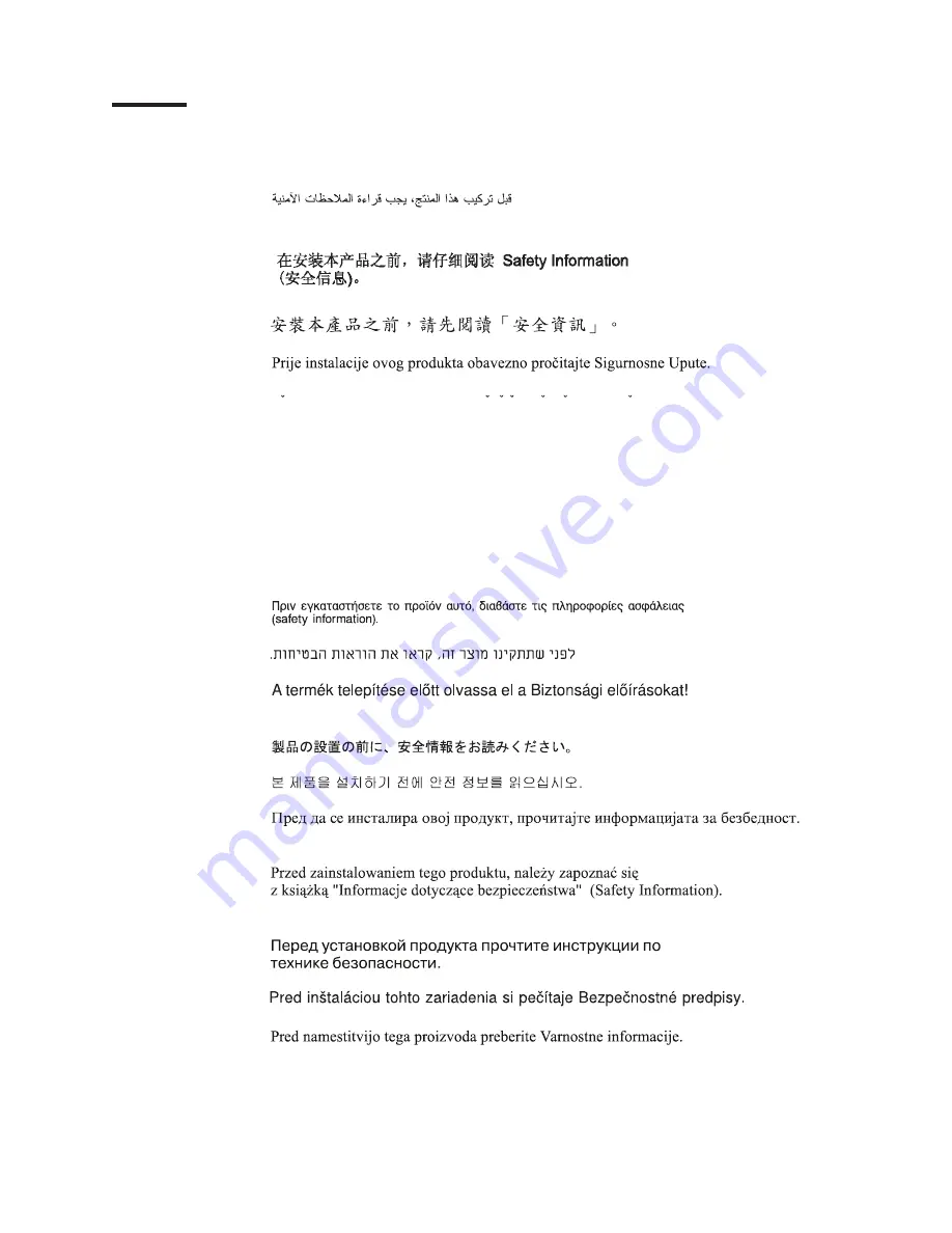
Before


installing


this


product,


read


the


Safety


Information.


Antes


de


instalar


este


produto,


leia


as


Informações


de


Segurança.


Pred instalací tohoto produktu si prectete prírucku bezpecnostních instrukcí.


Læs


sikkerhedsforskrifterne,


før


du


installerer


dette


produkt.


Lees


voordat


u


dit


product


installeert


eerst


de


veiligheidsvoorschriften.


Ennen


kuin


asennat


tämän


tuotteen,


lue


turvaohjeet


kohdasta


Safety


Information.


Avant


d’installer


ce


produit,


lisez


les


consignes


de


sécurité.


Vor


der


Installation


dieses


Produkts


die


Sicherheitshinweise


lesen.


Prima


di


installare


questo


prodotto,


leggere


le


Informazioni


sulla


Sicurezza.


Les


sikkerhetsinformasjonen


(Safety


Information)


før


du


installerer


dette


produktet.


Antes


de


instalar


este


produto,


leia


as


Informações


sobre


Segurança.


Antes


de


instalar


este


producto,


lea


la


información


de


seguridad.


Läs


säkerhetsinformationen


innan


du


installerar


den


här


produkten.


©


Copyright


IBM


Corp.


2007


vii

Summary of Contents for 8853L6U

Page 1: ...BladeCenter HS21 Types 1885 and 8853 Problem Determination and Service Guide...

Page 2: ......

Page 3: ...BladeCenter HS21 Types 1885 and 8853 Problem Determination and Service Guide...

Page 4: ...Notices on page 117 and the Warranty and Support Information document on the IBM Documentation CD Tenth Edition November 2008 Copyright International Business Machines Corporation 2008 US Government U...

Page 5: ...server components 19 Installation guidelines 19 System reliability guidelines 20 Handling static sensitive devices 20 Returning a device or component 20 Removing the blade server from a BladeCenter u...

Page 6: ...nnection problems 86 Optional device problems 86 Power error messages 87 Power problems 89 Removable media drive problems 90 ServerGuide problems 91 Service processor problems 92 Software problems 92...

Page 7: ...ry return program 121 Electronic emission notices 122 Federal Communications Commission FCC statement 122 Industry Canada Class A emission compliance statement 123 Avis de conformit la r glementation...

Page 8: ...vi BladeCenter HS21 Types 1885 and 8853 Problem Determination and Service Guide...

Page 9: ...tuotteen lue turvaohjeet kohdasta Safety Information Avant d installer ce produit lisez les consignes de s curit Vor der Installation dieses Produkts die Sicherheitshinweise lesen Prima di installare...

Page 10: ...ver is not damaged loose or broken and observe any sharp edges 3 Check the power cord v Make sure that the third wire ground connector is in good condition Use a meter to measure third wire ground con...

Page 11: ...vailable to turn off the power if necessary When you are working with powered on electrical equipment use only one hand Keep the other hand in your pocket or behind your back to avoid creating a compl...

Page 12: ...fire water or structural damage v Disconnect the attached power cords telecommunications systems networks and modems before you open the device covers unless instructed otherwise in the installation...

Page 13: ...ces or regulations Statement 3 CAUTION When laser products such as CD ROMs DVD drives fiber optic devices or transmitters are installed note the following v Do not remove the covers Removing the cover...

Page 14: ...nd the power switch on the power supply do not turn off the electrical current supplied to the device The device also might have more than one power cord To remove all electrical current from the devi...

Page 15: ...this label attached There are no serviceable parts inside these components If you suspect a problem with one of these parts contact a service technician Statement 10 CAUTION Do not place any object on...

Page 16: ...xiv BladeCenter HS21 Types 1885 and 8853 Problem Determination and Service Guide...

Page 17: ...ut the server including how to install supported options and how to configure the server v Safety Information This document is in PDF on the IBM Documentation CD It contains translated caution and dan...

Page 18: ...nt or problem situations v Attention These notices indicate potential damage to programs devices or data An attention notice is placed just before the instruction or situation in which damage could oc...

Page 19: ...ement Interface IPMI firmware v ATI RN 50 ES1000 video controller v LSI 1064E Serial Attached SCSI SAS controller v Light path diagnostics v RS 485 interface for communication with the management modu...

Page 20: ...the following sequence to switch KVM control between blade servers NumLock NumLock blade_server_number Enter Where blade_server_number is the two digit number for the blade bay in which the blade ser...

Page 21: ...the request is being processed and then is lit when the ownership of the media tray has been transferred to the blade server It can take approximately 20 seconds for the operating system in the blade...

Page 22: ...t module the Wake on LAN feature can turn on the blade server Turning off the blade server When you turn off the blade server it is still connected to power through the BladeCenter unit The blade serv...

Page 23: ...quipped with power connector J164 Microprocessor 1 U6 Microprocessor 2 U7 SAS hard disk drive 0 J136 SAS hard disk drive 1 J137 Concurrent KVM connector J149 DIMM 4 J144 DIMM 3 J143 DIMM 2 J142 DIMM 1...

Page 24: ...SW3 Switch number Description SW3 Switch block 3 has eight switches v 1 BIOS backup page Off the BIOS starts from the primary BIOS page On the BIOS starts from the backup BIOS page v 2 Reserved v 3 Wa...

Page 25: ...press the light path diagnostics switch to light any error LEDs that were turned on during processing Diagnosing problems using the light path LEDs is described in Light path diagnostics on page 93 N...

Page 26: ...from the BladeCenter unit open the cover and press the light path diagnostics switch to light any error LEDs that were turned on during processing DIMM8 error LED Light path diagnostics DIMM7 error L...

Page 27: ...y program complete the following steps 1 Turn on the server 2 When the message Press F1 for Configuration Setup appears press F1 If an administrator password has been set you must type the administrat...

Page 28: ...e Ethernet controller designations that a blade server uses The routing of an Ethernet controller to a particular I O module bay depends on the type of blade server You can verify which Ethernet contr...

Page 29: ...onfiguration Setup Utility program see the Installation and User s Guide for information and instructions Important You must create the RAID array before you install the operating system on the blade...

Page 30: ...14 BladeCenter HS21 Types 1885 and 8853 Problem Determination and Service Guide...

Page 31: ...ree types v Tier 1 customer replaceable unit CRU Replacement of Tier 1 CRUs is your responsibility If IBM installs a Tier 1 CRU at your request you will be charged for the installation v Tier 2 custom...

Page 32: ...2 13 GH 1066 12M 40W model GNx 46M0601 4 Microprocessor 2 33 GHz 1333 4M 65W models E4x L4x NTx 42C1628 4 Microprocessor 2 33 GHz 1333 4M 40W model H1x 42C0629 4 Microprocessor 2 33 GHz 1333 6M 80W m...

Page 33: ...7x G1x G2x G3x G4x G5x G6x G7x GLx GNx H1x J1x J2x L1x L2x L3x L4x L5x L6x NTx R2x RLx 43W8577 Battery 3 0 volt all models 33F8354 Bezel NGB option 42C8564 BladeCenter Storage Expansion Unit 3 option...

Page 34: ...system service for optional IBM BladeCenter Memory and I O Expansion Blade all models 41Y5297 NEMO 1Gb 4 Port ethernet expansion card 44W4488 PCI I O expansion unit 3e option 43W4390 Expansion card M...

Page 35: ...ssues are addressed and that your blade server is ready to function at maximum levels of performance To download firmware updates for your blade server complete the following steps Note Changes are ma...

Page 36: ...r T unit use an electrostatic discharge ESD wrist strap especially when you will be handling modules options and blade servers To work properly the wrist strap must have a good contact at both ends to...

Page 37: ...different see the documentation for your BladeCenter unit for additional information Release handles open 1 Read the safety information that begins on page vii and Installation guidelines on page 19...

Page 38: ...the bay from which you removed the blade server remove it from the bay Attention You must install the blade server in the same blade bay from which you removed it Some blade server configuration info...

Page 39: ...or in any way block the ventilation holes on the blade server If you have changed the configuration of the blade server or if you are installing a different blade server from the one that you removed...

Page 40: ...teps Blade cover release Blade cover release 1 Read the safety information that begins on page vii and Installation guidelines on page 19 2 If the blade server is installed in a BladeCenter unit remov...

Page 41: ...that the slots at the rear slide down onto the pins at the rear of the blade server Before closing the cover check that all components are installed and seated correctly and that you have not left loo...

Page 42: ...s installed see Removing the blade server cover on page 24 for instructions 5 Remove the expansion unit a Press the blade cover release on each side of the blade server b Use the extraction device on...

Page 43: ...it so that the slots at the rear slide down onto the cover pins at the rear of the blade server 5 Close the expansion unit v If the expansion unit has an extraction device pivot the expansion unit clo...

Page 44: ...ssembly away from the blade server approximately 1 2 cm 0 5 inch 5 Disconnect the control panel cable from the control panel connector 6 Pull the bezel assembly away from the blade server 7 Store the...

Page 45: ...it on page 21 3 Remove the blade server cover see Removing the blade server cover on page 24 for instructions 4 If a Memory and I O Expansion Blade is installed remove it see Removing an expansion uni...

Page 46: ...on the BladeCenter unit or any unpainted metal surface on any other grounded rack component then remove the hard disk drive from the package Attention Do not press on the top of the drive Pressing the...

Page 47: ...lade DIMM 8 J19 DIMM 7 J18 DIMM 6 J21 DIMM 5 J20 To remove a DIMM complete the following steps DIMM Retaining clip 1 Read the safety information that begins Safety on page vii and Installation guideli...

Page 48: ...tched DIMMs Install the DIMMs in the following order Pair DIMM connectors First 1 J141 and 3 J143 Second 2 J142 and 4 J144 To set up a non mirrored memory configuration for a blade server with a Memor...

Page 49: ...MM 5 J20 To install a DIMM complete the following steps DIMM Retaining clip 1 Read the documentation that comes with the DIMM 2 Locate the DIMM connectors Determine the connectors into which you will...

Page 50: ...sion unit on page 27 9 Install the blade server cover see Installing the blade server cover on page 25 10 Install the blade server into the BladeCenter unit see Installing the blade server in a BladeC...

Page 51: ...ure Card 3 Slide the right side of the card the side of the card that is away from the concurrent KVM connector between the two tabs at the right side of the expansion card bracket then gently pivot t...

Page 52: ...blade server cover on page 24 for instructions 4 If a Memory and I O Expansion Blade is installed and you are removing the expansion card from the system board remove the Memory and I O Expansion Blad...

Page 53: ...narrow end of the card into the raised hook on the expansion card bracket then gently pivot the card into the expansion card connector Note For device driver and configuration information to complete...

Page 54: ...Removing the blade server cover on page 24 for instructions 4 If a Memory and I O Expansion Blade is installed and you are removing the expansion card from the system board remove the Memory and I O...

Page 55: ...nd slide the narrow end of the card into the raised hook on the expansion card bracket then gently pivot the wide end of the card into the expansion card connectors 3 Install the Memory and I O Expans...

Page 56: ...e expansion card standoffs and lift the card out of the blade server 6 If you are instructed to return the expansion card follow all packaging instructions and use any packaging materials for shipping...

Page 57: ...age vii and Installation guidelines on page 19 2 If the blade server is installed in a BladeCenter unit remove it see Removing the blade server from a BladeCenter unit on page 21 for instructions 3 Re...

Page 58: ...e manufacturer If your system has a module containing a lithium battery replace it only with the same module type made by the same manufacturer The battery contains lithium and can explode if not prop...

Page 59: ...ctor J164 complete the following steps to remove the power jumper Note A power jumper is not installed when a Memory and I O Expansion Blade is installed Power jumper 1 Read the safety information tha...

Page 60: ...ower jumper 1 Locate the power connector J164 on the system board 2 Place the power jumper into the power connector and press the power jumper until it is fully seated 3 Install the blade server cover...

Page 61: ...hermal material remains evenly distributed between each heat sink and microprocessor Notes v The heat sink FRU is packaged with the thermal material applied to the underside This thermal material is n...

Page 62: ...b Press firmly on the captive screws and loosen them with a screwdriver c Use your fingers to gently pull the heat sink from the processor Attention Do not use any tools or sharp objects to lift the r...

Page 63: ...it stops in the fully open position approximately a 135 angle as shown b Rotate the microprocessor retainer on the microprocessor socket from its closed position until it stops in the fully open posit...

Page 64: ...then align and place the heat sink on top of the microprocessor in the retention bracket thermal material side down Press firmly on the heat sink c Align the two screws on the heat sink with the holes...

Page 65: ...e Removing the bezel assembly on page 28 7 Remove all of the installed components in the following list from the system board assembly then place them on a non conductive surface or install them on th...

Page 66: ...page 47 v DIMMs See Installing a memory module on page 32 v Battery See Installing the battery on page 42 2 If the system board assembly is equipped with power connector J164 and a Memory and I O Expa...

Page 67: ...etection of a problem See POST for more information v Troubleshooting tables These tables list problem symptoms and actions to correct the problems See Troubleshooting tables on page 80 for more infor...

Page 68: ...ing microprocessor problems v Follow the suggested actions in the order in which they are listed in the Action column until the problem is solved v See Chapter 3 Parts listing Types 1885 and 8853 on p...

Page 69: ...chnician only Replace the system board assembly 1 2 3 DMA page register write read failed Trained service technician only Replace the system board assembly 1 2 4 RAM refresh verification failed 1 Rese...

Page 70: ...failed Trained service technician only Replace the system board assembly 2 2 2 Keyboard controller test failed 1 Check the function of the shared BladeCenter unit resources see Solving shared BladeCen...

Page 71: ...ents one at a time in the order shown restarting the blade server each time a DIMMs b Trained service technician only System board assembly 3 3 3 No operational memory in system Important In some memo...

Page 72: ...onents are FRUs v If an action step is preceded by Trained service technician only that step must be performed only by a trained service technician No beep symptom Action No beep and the blade server...

Page 73: ...t module event log in your BladeCenter unit lists messages according to the position of the blade server in the blade bays If a blade server is moved from one bay to another the management module even...

Page 74: ...uide To view the BMC log complete the following steps 1 Turn on the blade server 2 When the prompt Press F1 for Configuration Setup appears press F1 If you have set a power on password you must type t...

Page 75: ...d fault 1 Reseat the Concurrent KVM feature card 2 Replace the Concurrent KVM feature card BEM 1 fault 1 Reseat the following components one at a time in the order shown restarting the blade server ea...

Page 76: ...board Firmware BIOS halted System management bus error 1 Update the blade server firmware 2 Update the blade server and option device drivers Power jumper not present If the blade server is equipped...

Page 77: ...t the front bezel on the blade server is not blocked 4 Trained service technician only Replace microprocessor xx Firmware BIOS backup ROM corruption System board failure 1 Update the blade server firm...

Page 78: ...the latest levels CPU xx over temperature Make sure that the blade server is sufficiently cooled CPU xx fault Trained service technician only Replace microprocessor xx CPU xx disabled Trained service...

Page 79: ...order shown restarting the blade server each time a Battery b Trained service technician only Microprocessor 1 c Trained service technician only Microprocessor 2 3 Replace the following components one...

Page 80: ...ponents one at a time in the order shown restarting the blade server each time a Battery b Trained service technician only System board assembly 163 Time of day not set 1 Run the Configuration Setup U...

Page 81: ...Security hardware control logic error Trained service technician only Replace the system board assembly 187 VPD Serial Number not set Trained service technician only Replace the system board assembly...

Page 82: ...onents one at a time in the order shown restarting the blade server each time a Trained service technician only Microprocessor 1 b Trained service technician only Microprocessor 2 289 Memory error 1 R...

Page 83: ...kette drive configuration error 1 Check the function of the shared BladeCenter unit resources see Solving shared BladeCenter resource problems on page 108 2 Trained service technician only Replace the...

Page 84: ...sion Blade if one is installed c Trained service technician only System board assembly 1801 No more room for option ROM 1 Run the Configuration Setup Utility program and make sure that the PXE setting...

Page 85: ...nd I O Expansion Blade is installed reseat it 4 Replace the following components one at a time in the order shown restarting the blade server each time a Failed I O expansion card b Memory and I O Exp...

Page 86: ...s installed reseat it 4 Replace the following components one at a time in the order shown restarting the blade server each time a Failed I O expansion card b Memory and I O Expansion Blade if one is i...

Page 87: ...Blade is installed reseat it 4 Replace the following components one at a time in the order shown restarting the blade server each time a Failed I O expansion card b Memory and I O Expansion Blade if o...

Page 88: ...I O expansion card b Memory and I O Expansion Blade if one is installed c Trained service technician only System board assembly 1962 Boot sector error no operating system installed 1 Make sure that a...

Page 89: ...sor 1 b Trained service technician only Microprocessor 2 c Trained service technician only System board assembly 000197xx Processor Pxx failed BIST 1 Trained service technician only Reseat microproces...

Page 90: ...cian only System board assembly 00150300 SERR Received Target Abort Slot xx Vendor ID xxxx Device ID xxxx Status xxxx 1 If a Memory and I O Expansion Blade is installed reseat it 2 Reseat the I O expa...

Page 91: ...rained service technician only System board assembly 00150600 PERR Primary Write parity error Slot xx Vendor ID xxxx Device ID xxxx Status xxxx 1 If a Memory and I O Expansion Blade is installed resea...

Page 92: ...x Device ID xxxx Status xxxx 1 If a Memory and I O Expansion Blade is installed reseat it 2 Reseat the I O expansion card in slot xx then restart the blade server 3 Replace the following components on...

Page 93: ...tional data for debug Check error codes 00151100 00151200 and 00151300 for action 00151352 Processor Machine Check Data b Status xxxx xxxx xxxx xxxx Additional data for debug Check error codes 0015110...

Page 94: ...ry DIMMs 00151801 Running from Mirrored Memory Image 1 Reseat DIMM See error code 00151500 to determine which DIMM to reseat or replace 2 Replace DIMM See error code 00151500 to determine which DIMM t...

Page 95: ...lem is caused by the hardware or by the software you can use the diagnostic programs to confirm that the hardware is working correctly v When you run the diagnostic programs a single problem might cau...

Page 96: ...bleshooting tables if necessary see Solving undetermined problems on page 112 v Yes Run the diagnostic programs see Running the diagnostic programs on page 98 If you receive an error see Diagnostic er...

Page 97: ...a new one The blade server stops responding during the Fixed Disk or SAS Attached Disk diagnostic test Remove the hard disk drive that was being tested when the blade server stopped responding and run...

Page 98: ...blems 1 Make sure that the keyboard video mouse select button LED on the front of the blade server is lit indicating that the blade server is connected to the shared keyboard and mouse 2 Check the fun...

Page 99: ...v If a DIMM was disabled by the user or by POST run the Configuration Setup Utility program and enable the DIMM 3 Reseat the DIMM and the Memory and I O Expansion Blade if one is installed 4 Replace...

Page 100: ...OST indicating that the startup boot microprocessor is not working correctly 1 Trained service technician only Reseat microprocessor 1 2 Trained service technician only Remove microprocessor 2 and res...

Page 101: ...ight sound during POST followed by a blank display screen If this occurs and the Boot Fail Count feature in the Start Options of the Configuration Setup Utility program is set to Enabled its default s...

Page 102: ...assembly Optional device problems v Follow the suggested actions in the order in which they are listed in the Action column until the problem is solved v See Chapter 3 Parts listing Types 1885 and 88...

Page 103: ...Expansion Blade if one is installed b Trained service technician only System board assembly VRD Power Good fault 1 Reseat the blade server 2 Check the function of the shared BladeCenter unit resource...

Page 104: ...e problems on page 108 3 Trained service technician only Replace the system board assembly System under recommended voltage for 0 9v Informational only Note If problem persists perform the following t...

Page 105: ...n the blade server remove it and restart the blade server If the blade server now starts you might have installed more devices than the power to that blade bay supports 7 If you tried another blade se...

Page 106: ...power management policies in the operating system for the blade server b Trained service technician only Replace the system board assembly Removable media drive problems The removable media CD DVD or...

Page 107: ...CD or DVD drive diskette drive and USB port Note Because the BladeCenter unit uses USB to communicate with the media tray devices switching ownership of the media tray to another blade server is the...

Page 108: ...monitor failure Disconnect the BladeCenter unit from all electrical sources wait for 30 seconds reconnect the BladeCenter unit to the electrical sources and restart the blade server If the problem rem...

Page 109: ...blade server When an error occurs LEDs can be lit throughout the blade server to help identify the source of the error After you remove the blade server you can press and hold the light path diagnost...

Page 110: ...e error LED SAS 0 hard disk drive error LED Battery error LED Power jumper error LED if equipped Microprocessor 1 error LED Microprocessor 2 error LED Light path diagnostics panel DIMM 4 error LED DIM...

Page 111: ...ory and I O Expansion Blade SBRD LP 1 LP 2 Memory and I O expansion blade system board error LED System board light path LED Memory and I O expansion blade light path LED Light path diagnostics switch...

Page 112: ...ported 2 Reseat the DIMM that is indicated by the lit LED 3 Replace the DIMM that is indicated by the lit LED Note Multiple DIMM LEDs do not necessarily indicate multiple DIMM failures If more than on...

Page 113: ...ce the system board assembly TEMP Over temperature error The system temperature has exceeded a threshold level 1 Check the function of the shared BladeCenter unit resources see Solving shared BladeCen...

Page 114: ...her error messages usually will not occur the next time you run the diagnostic programs Exception If there are multiple error codes or light path diagnostics LEDs that indicate a microprocessor error...

Page 115: ...ion problem or the hardware might be missing or is not being recognized The result is followed by an error code or other additional information about the error Viewing the test log To view the test lo...

Page 116: ...umn until the problem is solved v See Chapter 3 Parts listing Types 1885 and 8853 on page 15 to determine which components are CRUs and which components are FRUs v If an action step is preceded by Tra...

Page 117: ...lade server in the BladeCenter unit and restart it If problem persists perform the following tasks in the order shown restarting the blade server each time 1 Remove the cKVM feature card if installed...

Page 118: ...it If problem persists perform the following tasks in the order shown restarting the blade server each time 1 Shutdown and remove the blade server from the BladeCenter unit then remove the Blade Stora...

Page 119: ...pdate the BMC firmware 4 Trained service technician only Replace the system board assembly 166 410 001 System Management Failed BMC indicates failure in I2C bus test Shutdown and remove the blade serv...

Page 120: ...the test again 2 Update the BMC firmware see Firmware updates on page 11 3 Trained service technician only Replace the system board assembly 166 407 001 System Management Failed BMC indicates failure...

Page 121: ...emory and I O Expansion Blade 201 xxx n99 Multiple DIMM failure see error text Note n number of failing pair see Installing a memory module on page 32 1 See the error text for failing DIMMs 2 If a Mem...

Page 122: ...ard management controller will detect the error and automatically switch to the backup page to start the blade server If this happens a POST message Booted from backup POST BIOS image is displayed The...

Page 123: ...Update the BIOS Attention Do not restart the blade server at this time 16 When the update is complete remove the flash diskette from the diskette drive 17 Turn off the blade server and remove it from...

Page 124: ...or the Hardware Maintenance Manual and Troubleshooting Guide for your BladeCenter unit and other BladeCenter component documentation for additional information If the problem cannot be solved see Solv...

Page 125: ...m with the blade server See Keyboard or mouse problems on page 82 Media tray problems To check for problems with the media tray removable media drives and USB ports complete the following steps until...

Page 126: ...rking properly b Continue with step 6 6 For problems affecting one or more of the removable media drives a Reseat the following components 1 Removable media drive cable if applicable 2 Removable media...

Page 127: ...information 4 Replace the management module see the documentation for your BladeCenter unit If these steps do not resolve the problem it is likely a problem with the blade server See Network connectio...

Page 128: ...nt diskette drive read write errors make sure that the distance between the monitor and any diskette drive is at least 76 mm 3 in 2 Check for correct management module operation see the documentation...

Page 129: ...n for the BladeCenter unit and management module for more information 3 Turn off the blade server 4 Remove the blade server from the BladeCenter unit and remove the cover 5 Remove or disconnect the fo...

Page 130: ...d before v Diagnostic program type and version level v Hardware configuration print screen of the system summary v BIOS code level v Operating system type and version level You can solve some problems...

Page 131: ...by following the troubleshooting procedures that IBM provides in the online help or in the documentation that is provided with your IBM product The documentation that comes with IBM systems also descr...

Page 132: ...ported by Support Line in your country or region see http www ibm com services sl products For more information about Support Line and other IBM services see http www ibm com services or see http www...

Page 133: ...10504 1785 U S A INTERNATIONAL BUSINESS MACHINES CORPORATION PROVIDES THIS PUBLICATION AS IS WITHOUT WARRANTY OF ANY KIND EITHER EXPRESS OR IMPLIED INCLUDING BUT NOT LIMITED TO THE IMPLIED WARRANTIES...

Page 134: ...es other countries or both Adobe and PostScript are either registered trademarks or trademarks of Adobe Systems Incorporated in the United States other countries or both UNIX is a registered trademark...

Page 135: ...s no representations or warranties with respect to non IBM products Support if any for the non IBM products is provided by the third party not IBM Some software might differ from its retail version if...

Page 136: ...t de recyclage applicables aux syst mes utilis s travers l Union europ enne Conform ment la directive ladite tiquette pr cise que le produit sur lequel elle est appos e ne doit pas tre jet mais tre r...

Page 137: ...an Union Notice This mark applies only to countries within the European Union EU Batteries or packaging for batteries are labeled in accordance with European Directive 2006 66 EC concerning batteries...

Page 138: ...Regulations Title 22 Division 4 5 Chapter 33 Best Management Practices for Perchlorate Materials This product part may include a lithium manganese dioxide battery which contains a perchlorate substan...

Page 139: ...ngdom European Union EMC Directive conformance statement This product is in conformity with the protection requirements of EU Council Directive 2004 108 EC on the approximation of the laws of the Memb...

Page 140: ...Class A warning statement Chinese Class A warning statement Japanese Voluntary Control Council for Interference VCCI statement 124 BladeCenter HS21 Types 1885 and 8853 Problem Determination and Servi...

Page 141: ...7 concurrent KVM card installing 35 removing 34 configuration Configuration Setup Utility 11 configuration continued minimum 113 ServerGuide Setup and Installation CD 11 Configuration Setup Utility p...

Page 142: ...ed functions 3 intermittent problems 81 J jumpers Memory and I O Expansion Blade 9 jumpers system board 8 L LEDs activity 5 blade error 5 error locations 93 information 5 light path diagnostics viewin...

Page 143: ...ard disk drive installing 30 removing 29 SAS RAID configure an array 13 Serial Attached SCSI SAS drive connectors 7 ServerGuide problems 91 Setup and Installation CD 11 service processor error codes 1...

Page 144: ...video problems 85 See monitor problems W web site publication ordering 115 support 115 support line telephone numbers 116 128 BladeCenter HS21 Types 1885 and 8853 Problem Determination and Service Gui...

Page 145: ......

Page 146: ...Part Number 49Y0053 Printed in USA 1P P N 49Y0053...

Reviews: