background image

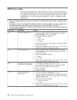
POST


error


codes


The


following


table


provides


an


abbreviated


list


of


the


error


codes


and


messages


that


might


appear


during


POST.


See


the


Problem


Determination


and


Service


Guide


on


the


IBM


Documentation


CD


for


more


information


about


the


POST


error


codes


and


messages.


Go


to


http://www.ibm.com/support/


to


check


for


updated


technical


information.


v


Follow


the


suggested


actions


in


the


order


in


which


they


are


listed


in


the


Action


column


until


the


problem


is


solved.


v


See


the


parts


listing


in


the


Problem


Determination


and


Service


Guide


to


determine


which


components


are


customer


replaceable


units


(CRU)


and


which


components


are


field


replaceable


units


(FRU).


v


If


an


action


step


is


preceded


by


“(Trained


service


technician


only),”


that


step


must


be


performed


only


by


a


trained


service


technician.


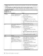
Error


code


Description


Action


162


Device


configuration


error.


1.


Run


the


Configuration/Setup


Utility


program,


select


Load


Default


Settings

,


and


save


the


settings.


2.


Reseat


the


following


components:


a.


Battery


b.


Failing


device


c.


I/O


board

3.


Remove


the


battery


for


60


minutes;


then,


reinstall


the


battery


and


restart


the


server.


4.


Replace


the


components


listed


in


step


2


one


at


a


time,


in


the


order


shown,


restarting


the


server


each


time.


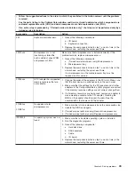
163


Real-time


clock


error.


1.


Run


the


Configuration/Setup


Utility


program,


select


Load


Default


Settings

,


make


sure


the


date


and


time


are


correct,


and


save


the


settings.


2.


Reseat


the


following


components:


a.


Battery


b.


I/O


board

3.


Replace


the


components


listed


in


step


2


one


at


a


time,


in


the


order


shown,


restarting


the


server


each


time.


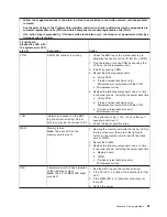
289


A


DIMM


has


been


disabled


by


the


user


or


by


the


system.


1.


If


the


DIMM


was


disabled


by


the


user,


run


the


Configuration/Setup


Utility


program


and


enable


the


DIMM.


2.


Make


sure


that


the


DIMM


is


installed


correctly.


3.


Reseat


the


DIMM.


4.


Replace


the


DIMM.


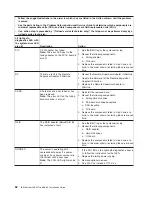
301


Keyboard


or


keyboard


controller


error.


1.


If


you


have


installed


a


USB


keyboard,


run


the


Configuration/Setup


Utility


program


and


enable


keyboardless


operation


to


prevent


the


POST


error


message


301


from


being


displayed


during


startup.


2.


Reseat


the


following


components:


a.


Keyboard


connection


b.


I/O


board

3.


Replace


the


components


listed


in


step


2


one


at


a


time,


in


the


order


shown,


restarting


the


server


each


time.


48


IBM


System


x3850


Type


8863:


Installation


Guide

Summary of Contents for 88631SU - System x3850 - 8863

Page 1: ...ility Documentation CD Installation Guide Go to the Server Support flowchart Cable the server and options Start the server Install options Drives Microprocessors Adapters Memory Did the server start correctly Yes No Use ServerGuide to set up and configure hardware Did configuration complete Use ServerGuide to install operating system Install applications such as IBM systems management software and...

Page 2: ... that all optional devices you installed are on the ServerProven list at http www ibm com servers eserver serverproven compat us Is the server working correctly Is the problem solved Hardware or software problem View support telephone numbers at http www ibm com planetwide View information about IBM Support Line at or view support telephone numbers at http www ibm com services sl products http www...

Page 3: ...IBM System x3850 Type 8863 Installation Guide ...

Page 4: ...ge 67 and the Warranty and Support Information document on the IBM Documentation CD Fourth Edition April 2006 Copyright International Business Machines Corporation 2006 All rights reserved US Government Users Restricted Rights Use duplication or disclosure restricted by GSA ADP Schedule Contract with IBM Corp ...

Page 5: ...pleting the installation 23 Connecting the cables 23 Updating the server configuration 24 Chapter 3 Server controls connectors LEDs and power 25 Front view 25 Rear view 26 Server power features 28 Turning on the server 28 Turning off the server 28 Chapter 4 Configuring the server 31 Using the ServerGuide Setup and Installation CD 31 Using the Configuration Setup Utility program 31 Installing and u...

Page 6: ...ll 65 Using the documentation 65 Getting help and information from the World Wide Web 66 Software service and support 66 Hardware service and support 66 Notices 67 Edition notice 67 Trademarks 68 Important notes 68 Product recycling and disposal 69 Battery return program 70 Electronic emission notices 71 Federal Communications Commission FCC statement 71 Industry Canada Class A emission compliance...

Page 7: ...talleert eerst de veiligheidsvoorschriften Ennen kuin asennat tämän tuotteen lue turvaohjeet kohdasta Safety Information Avant d installer ce produit lisez les consignes de sécurité Vor der Installation dieses Produkts die Sicherheitshinweise lesen Prima di installare questo prodotto leggere le Informazioni sulla Sicurezza Les sikkerhetsinformasjonen Safety Information før du installerer dette pro...

Page 8: ...d versions of the caution or danger statement in the IBM Safety Information book For example if a caution statement begins with a number 1 translations for that caution statement appear in the IBM Safety Information book under statement 1 Be sure to read all caution and danger statements in this documentation before performing the instructions Read any additional safety information that comes with...

Page 9: ...equipment when there is evidence of fire water or structural damage v Disconnect the attached power cords telecommunications systems networks and modems before you open the device covers unless instructed otherwise in the installation and configuration procedures v Connect and disconnect cables as described in the following table when installing moving or opening covers on this product or attached...

Page 10: ...tatement 3 CAUTION When laser products such as CD ROMs DVD drives fiber optic devices or transmitters are installed note the following v Do not remove the covers Removing the covers of the laser product could result in exposure to hazardous laser radiation There are no serviceable parts inside the device v Use of controls or adjustments or performance of procedures other than those specified herei...

Page 11: ... power control button on the device and the power switch on the power supply do not turn off the electrical current supplied to the device The device also might have more than one power cord To remove all electrical current from the device ensure that all power cords are disconnected from the power source 1 2 Safety ix ...

Page 12: ... and energy levels are present inside any component that has this label attached There are no serviceable parts inside these components If you suspect a problem with one of these parts contact a service technician Statement 10 CAUTION Do not place any object on top of rack mounted devices x IBM System x3850 Type 8863 Installation Guide ...

Page 13: ...d documentation and technical updates 1 See http www ibm com support 2 In the Browse by topic section click Publications 3 On the Publications page in the Brand field select Servers 4 In the Family field select System x3850 5 Click Continue The server comes with an IBM ServerGuide Setup and Installation CD to help you configure the hardware install device drivers and install the operating system T...

Page 14: ...v 32 MB of RAM v Adobe Acrobat Reader 3 0 or later or xpdf which comes with Linux operating systems Acrobat Reader software is included on the CD and you can install it when you run the Documentation Browser Using the Documentation Browser Use the Documentation Browser to browse the contents of the CD read brief descriptions of the documents and view documents using Adobe Acrobat Reader or xpdf Th...

Page 15: ...of the most occurrences Click a document to view it and press Crtl F to use the Acrobat search function or Alt F to use the xpdf search function within the document Click Help for detailed information about using the Documentation Browser Notices and statements used in this document The caution and danger statements that appear in this document are also in the multilingual Safety Information docum...

Page 16: ...ll Integrated functions v Baseboard management controller v IBM EXA 32 Chipset with integrated memory and I O controller v Service processor support for Remote Supervisor Adapter II SlimLine v Light path diagnostics v Three Universal Serial Bus USB ports Two on rear of server One on front of server v Broadcom 5704C dual 10 100 1000 Gigabit Ethernet controllers v ATI 7000 M video 16 MB video memory...

Page 17: ...nge can also indicate touch points on hot swap components See the instructions for removing or installing a specific hot swap component for any additional procedures that you might have to perform before you remove or install the component The following illustration shows the major components in the server xSer ier 365 Memory card Hot swap power supply I O board Hot swap fans 92 mm Hot swap fans 8...

Page 18: ...6 IBM System x3850 Type 8863 Installation Guide ...

Page 19: ...d electrical outlets for the server monitor and other devices v Back up all important data before you make changes to disk drives v Have a small flat blade screwdriver available v You do not have to turn off the server to install or replace hot swap power supplies hot swap fans hot plug adapters or hot plug Universal Serial Bus USB devices However you must turn off the server when performing any s...

Page 20: ...r components when the server is powered on might cause the server to halt which could result in the loss of data To avoid this potential problem always use an electrostatic discharge wrist strap or other grounding system when working inside the server with the power on v Avoid wearing loose fitting clothing on your forearms Button long sleeved shirts before working inside the server do not wear cu...

Page 21: ...for at least 2 seconds This drains static electricity from the package and from your body v Remove the device from its package and install it directly into the server without setting down the device If it is necessary to set down the device put it back into its static protective package Do not place the device on the server cover or on a metal surface v Take additional care when handling devices d...

Page 22: ...es 1 When you turn on the server check the hard disk drive status LEDs to make sure that the hard disk drive is operating correctly If the amber hard disk drive status LED for a drive is lit continuously that drive is faulty and must be replaced If the green hard disk drive activity LED is flashing the drive is being accessed 2 If the server will be configured for RAID operation using an optional ...

Page 23: ... operate v When you install additional DIMMs on a memory card be sure to install them in pairs All the DIMM pairs on each memory card must be the same size and type v Install the DIMMs on each memory card in the order shown in the following table You must install at least one pair of DIMMs on each memory card See the User s Guide on the IBM Documentation CD for additional memory configuration inst...

Page 24: ... DIMM Installing a memory module Attention Static electricity that is released to internal server components when the server is powered on might cause the server to halt which could result in the loss of data To avoid this potential problem always use an electrostatic discharge wrist strap or other grounding system when working inside the server with the power on Complete the following steps to in...

Page 25: ...IMM connectors facing up Attention To avoid breaking the DIMM retaining clips or damaging the DIMM connectors open and close the clips gently 5 Open the retaining clip on each end of the DIMM connector 6 Touch the static protective package that contains the DIMM to any unpainted metal surface on the outside of the server Then remove the DIMM from the package 7 Turn the DIMM so that the DIMM keys a...

Page 26: ...ling a memory card At least one memory card with one pair of DIMMs must be installed for the server to operate correctly Attention Static electricity that is released to internal server components when the server is powered on might cause the server to halt which could result in the loss of data To avoid this potential problem always use an electrostatic discharge wrist strap or other grounding sy...

Page 27: ...ress the memory card into the connector and close the locking levers If you have other options to install or remove do so now otherwise go to Completing the installation on page 23 Chapter 2 Installing options 15 ...

Page 28: ...rates properly v Install the microprocessors in the order shown in the following illustration 1 2 3 4 Complete the following steps to install an additional microprocessor 1 Read the safety information beginning on page v and Installation guidelines on page 7 2 Turn off the server and peripheral devices and disconnect the power cords and any USB cable that might be connected to the USB port on the ...

Page 29: ...the server 5 Remove the microprocessor tray a Open the microprocessor tray release latch 1 Microprocessor tray lever Microprocessor tray lever Microprocessor tray retention latch both sides of tray Air baffle Microprocessor tray release latch Chapter 2 Installing options 17 ...

Page 30: ...sor baffle VRM 4 F R O N T Air baffle F R O N T F R O N T F R O N T 7 Remove the microprocessor baffle from a microprocessor socket and store it for future use If you remove a microprocessor you must install a microprocessor baffle to prevent the server from over heating Microprocessor baffle Heat sink retention clip 8 Open the heat sink retention clip a Press down on one side of the heat sink ret...

Page 31: ... microprocessor into the socket Microprocessor orientation indicator Microprocessor release lever Microprocessor connector Microprocessor 13 Close the microprocessor release lever to secure the microprocessor 14 Remove the heat sink from its package and remove the cover from the bottom of the heat sink 15 Position the heat sink above the microprocessor then press the heat sink into place and close...

Page 32: ...all the Remote Supervisor Adapter II SlimLine I O board Remote Supervisor Adapter II SlimLine Remote Supervisor Adapter II SlimLine connector Standoff Standoff Complete the following steps to install a Remote Supervisor Adapter II SlimLine 1 Insert the rear 1 of the adapter into the rear standoff then rotate the front 2 of the adapter into the front standoff 2 Press the Remote Supervisor Adapter I...

Page 33: ...t strap or other grounding system when working inside the server with the power on To install a hot plug PCI or PCI X adapter complete the following steps Note For hot pluggable adapters make sure that the PCI hot plug device driver is installed For details see the documentation that comes with the adapter For more detailed instructions and information about installing PCI PCI X adapters see the s...

Page 34: ...s off c Remove the expansion slot cover d Carefully grasp the adapter by its top edge or upper corners and align it with the connector on the PCI X board e If necessary remove the adapter guide before installing a full length adapter f Press the adapter firmly into the adapter connector g Push down on the blue PCI X retaining bar to stabilize the adapter h Close the tab then push down on the orang...

Page 35: ... server on page 28 before connecting any cables to or disconnecting any cables from the server See the documentation that comes with optional devices for additional cabling instructions It might be easier for you to route cables before you install certain options Cable identifiers are printed on the cables that come with the server and options Use these identifiers to connect the cables to the cor...

Page 36: ... with each option for information about installing device drivers The server comes with at least one microprocessor on the microprocessor board If more than one microprocessor is installed the server can operate as a symmetric multiprocessing SMP server You might have to upgrade the operating system to support SMP For more information see the section about using the ServerGuide Setup and Installat...

Page 37: ...drive activity LED On some server models each hot swap hard disk drive has an activity LED When this LED is flashing it indicates that the drive is in use Operator information panel This panel contains controls and LEDs The following illustration shows the controls and LEDs on the operator information panel Power control button Power on LED USB connector Hard disk drive activity LED Information LE...

Page 38: ... not present or the power supply or the LED itself has failed Note If this LED is off it does not mean that there is no electrical power in the server The LED might be burned out To remove all electrical power from the server you must disconnect the power cords from the electrical outlets DVD eject button Press this button to release a CD or DVD from the DVD drive DVD drive activity LED When this ...

Page 39: ...85 connector Use this connector to connect to an iSeries server when an Integrated xSeries Adapter IXA is installed I O board error LED This LED is on the I O board and is visible on the rear of the server When this LED is lit it indicates that there is a problem with the I O board Gigabit Ethernet 2 activity LED This LED is on the Gigabit Ethernet 2 connector When this LED flashes it indicates th...

Page 40: ...is connected to an Advanced System Management interconnect network that contains at least one server with an optional Remote Supervisor Adapter II SlimLine installed the server can be turned on from the Remote Supervisor Adapter II SlimLine user interface v If your operating system supports the systems management software for an optional Remote Supervisor Adapter II SlimLine the systems management...

Page 41: ... and turn off the server if your operating system supports this feature v If the operating system stops functioning you can press and hold the power control button for more than 4 seconds to turn off the server v If the server is connected to an Advanced System Management interconnect network that contains at least one server with an optional Remote Supervisor Adapter II SlimLine installed the ser...

Page 42: ...30 IBM System x3850 Type 8863 Installation Guide ...

Page 43: ... you install the operating system For information about the supported operating system versions see the label on the CD If the ServerGuide Setup and Installation CD did not come with the server you can download the latest version from http www ibm com pc qtechinfo MIGR 4ZKPPT html Complete the following steps to start the ServerGuide Setup and Installation CD 1 Insert the CD and restart the server...

Page 44: ...formation and identify the server You can also save one or more commands as a text file and run the file as a script v Serial over LAN Establish a Serial over LAN SOL connection to manage servers from a remote location You can remotely view and change the BIOS settings restart the server identify the server and perform other management functions Any standard Telnet client application can access th...

Page 45: ...to Planar Ethernet 2 you must also set Run PXE only on selected Planar NIC to Enabled f Press Esc to exit the Start Options section of the Configuration Setup Utility program g Select Save Settings then press Enter h Press Enter to confirm i Select Exit Setup then press Enter j Make sure that Yes exit the Setup Utility is selected then press Enter Configuring Linux For SOL operation on the server ...

Page 46: ...nf file a Add the following text to the end of the first default linux line Monitor b Comment out the map boot map line by adding a at the beginning of the line c Comment out the message boot message line by adding a at the beginning of the line d Add the following line before the first image line This will allow you to only Monitor the OS boot via SOL e Add the following text to the end of the fi...

Page 47: ...install boot boot b message boot message linear image boot vmlinuz 2 4 9 e 12smp label linux initrd boot initrd 2 4 9 e 12smp img read only root dev hda6 image boot vmlinuz 2 4 9 e 12 label linux up initrd boot initrd 2 4 9 e 12 img read only root dev hda6 Chapter 4 Configuring the server 35 ...

Page 48: ...nux operating system starts a LILO boot prompt is displayed instead of the graphical user interface Press Tab at this prompt to install all of the boot options that are listed To load the operating system in interactive mode type linux Interact and press Enter GRUB configuration If you are using GRUB complete the following steps to modify the boot grub grub conf file 1 Comment out the splashimage ...

Page 49: ...ted by anaconda Note that you do not have to rerun grub after making changes to this file NOTICE You have a boot partition This means that all kernel and initrd paths are relative to boot eg root hd0 0 kernel vmlinuz version ro root dev hda6 initrd initrd version img boot dev hda default 0 timeout 10 splashimage hd0 0 grub splash xpm gz title Red Hat Enterprise Linux ES 2 4 9 e 12smp root hd0 0 ke...

Page 50: ...rd initrd 2 4 9 e 12 img You must restart the Linux operating system after completing these procedures for the changes to take effect and to enable SOL SUSE SLES 8 0 configuration Note This procedure is based on a default installation of SUSE Linux Enterprise Server SLES 8 0 The file names structures and commands might be different for other versions of SUSE Linux To configure the general Linux pa...

Page 51: ...color white blue black light gray default 0 timeout 8 title linux kernel hd0 1 boot vmlinuz root dev hda2 acpi oldboot vga 791 1 initrd hd0 1 boot initrd title floppy root chainloader 1 title failsafe kernal hd0 1 boot vmlinuz shipped root dev hda2 ide nodma apm off vga normal nosmp 1 disableapic maxcpus 0 3 initrd hd0 1 boot initrd shipped Note 1 The kernel line is shown with a line break In your...

Page 52: ...ystem Write down the boot entry ID for use in the next step 2 To enable the Microsoft Windows Emergency Management System EMS at a Windows command prompt type bootcfg EMS ON PORT COM1 BAUD 19200 ID boot_id where boot_id is the boot entry ID from step 1b then press Enter 3 To verify that the EMS console is redirected to the COM2 serial port a Type bootcfg at a Windows command prompt then press Ente...

Page 53: ...ure for the changes to take effect and to enable SOL Installing the OSA SMBridge management utility program Complete the following steps to install the OSA SMBridge management utility program on a server running a Windows operating system 1 Go to http www ibm com support download the utility program and create the OSA BMC Management Utility CD 2 Insert the OSA BMC Management Utility CD into the dr...

Page 54: ...copies files to the following directories etc init d SMBridge etc smbridge cfg usr sbin smbridged var log smbridge License txt var log smbridge Readme txt The utility starts automatically when the server is started You can also locate the ect init d directory to start the utility and use the following commands to manage the utility smbridge status smbridge start smbridge stop smbridge restart Usin...

Page 55: ... utility program provides the following remote management capabilities v CLI command line interface mode Use CLI mode to remotely perform power management and system identification control functions over a LAN or serial port interface from a command line interface Use CLI mode also to remotely view the BMC system event log Use the following commands in CLI mode identify Control the system locator ...

Page 56: ...oller and the User s Guide on the IBM Documentation CD If your server comes with an operating system installed such as Microsoft Windows 2000 Datacenter Server see the software documentation that comes with the server for configuration information Using the PXE boot agent utility program The Preboot Execution Environment PXE boot agent utility program is part of the BIOS code You can use it to spe...

Page 57: ... shown in the drop down list follow the instructions on the Web page to download the latest version 2 Install the IBM Director program 3 Download and install any applicable updates or interim fixes for the server a See http www ibm com b Click Support downloads c Click Downloads drivers d In the search field type director 8863 and click Submit e Select any applicable update or interim fix that you...

Page 58: ...46 IBM System x3850 Type 8863 Installation Guide ...

Page 59: ...ooting charts These charts list problem symptoms and steps to correct the problems See Troubleshooting charts on page 51 for more information v Diagnostic programs and error messages The system diagnostic programs are provided in ROM These programs test the major components of the server See the Problem Determination and Service Guide on the IBM Documentation CD for more information v Light path d...

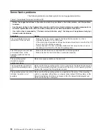
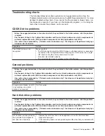
Page 60: ...ve the battery for 60 minutes then reinstall the battery and restart the server 4 Replace the components listed in step 2 one at a time in the order shown restarting the server each time 163 Real time clock error 1 Run the Configuration Setup Utility program select Load Default Settings make sure the date and time are correct and save the settings 2 Reseat the following components a Battery b I O ...

Page 61: ...e If a microprocessor or the microprocessor tray must be replaced call for service 00180xxx A PCI adapter has requested memory resources that are not available 1 Change the order of the adapters in the PCI slots Make sure that the boot device is positioned early in the scan order 2 Make sure that the settings for the PCI adapter and all other adapters in the Configuration Setup Utility program are...

Page 62: ... drive is installed make sure that only one drive is set as the primary drive Start the CD from the primary drive The RAID program cannot view all installed drives or the operating system cannot be installed v Make sure that there are no duplicate IDs or IRQ assignments v Make sure that the hard disk drive is connected correctly The operating system installation program continuously loops Make mor...

Page 63: ...r is installed for the CD DVD drive General problems v Follow the suggested actions in the order in which they are listed in the Action column until the problem is solved v See the parts listing in the Problem Determination and Service Guide to determine which components are customer replaceable units CRU and which components are field replaceable units FRU v If an action step is preceded by Train...

Page 64: ...Trained service technician only that step must be performed only by a trained service technician Symptom Action A problem occurs only occasionally and is difficult to diagnose Make sure that v All cables and cords are connected securely to the rear of the server and attached devices v When the server is turned on air is flowing from the rear of the server at the fan grille If there is no airflow t...

Page 65: ...Service Guide to determine which components are customer replaceable units CRU and which components are field replaceable units FRU v If an action step is preceded by Trained service technician only that step must be performed only by a trained service technician Symptom Action The amount of system memory displayed is less than the amount of installed physical memory Make sure that v The DIMMs are...

Page 66: ... and Service Guide to determine which components are customer replaceable units CRU and which components are field replaceable units FRU v If an action step is preceded by Trained service technician only that step must be performed only by a trained service technician Symptom Action The screen is blank Make sure that v The server power cord is connected to the server and a working electrical outle...

Page 67: ...If the problem remains call for service Wrong characters appear on the screen If the wrong language is displayed update the BIOS code with the correct language If the problem remains call for service Option problems v Follow the suggested actions in the order in which they are listed in the Action column until the problem is solved v See the parts listing in the Problem Determination and Service G...

Page 68: ...s are customer replaceable units CRU and which components are field replaceable units FRU v If an action step is preceded by Trained service technician only that step must be performed only by a trained service technician Symptom Action The server does not turn on v Make sure that the server power cord is connected to the server and a working electrical outlet v Make sure that the type of memory t...

Page 69: ...Software problems v Follow the suggested actions in the order in which they are listed in the Action column until the problem is solved v See the parts listing in the Problem Determination and Service Guide to determine which components are customer replaceable units CRU and which components are field replaceable units FRU v If an action step is preceded by Trained service technician only that ste...

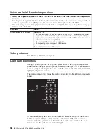
Page 70: ...vice driver is installed v Your operating system supports USB devices If the problem remains call for service Video problems See Monitor problems on page 54 Light path diagnostics Use light path diagnostics to diagnose system errors The light path diagnostics panel is inside the light path diagnostics drawer on the right front of the server To access the light path diagnostics panel slide the latc...

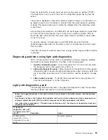
Page 71: ...he following order 1 Operator information panel Look at this panel first If an error has occurred the information LED or the system error LED is lit 2 Light path diagnostics panel Move the latch on the right front of the operator information panel to access the light path diagnostics panel Note any LEDs that are lit and then close the panel For LED locations see the illustration on page 48 3 LEDs ...

Page 72: ... the dc power LED on one power supply might be off 1 Reinstall the removed power supply 2 Check the individual power supply LEDs to find the failing power supply 3 Reseat the following components a Failing power supply b Trained service technician only Power backplane 4 Replace the components listed in step 3 one at a time in the order shown restarting the server each time 5 If a 240 V ac fault ha...

Page 73: ...e in the order shown restarting the server each time a Failing VRM b Trained service technician only Microprocessor associated with the VRM c Trained service technician only Microprocessor tray LOG Information is present in the BMC log and system error log One or both logs may be full or close to full 1 The system error log is 75 full save the log if necessary and clear it 2 Check the log for poss...

Page 74: ...e firmware for the Remote Supervisor Adapter II SlimLine 3 Replace the Remote Supervisor Adapter II SlimLine DASD A hard disk drive has failed or has been removed Note The error LED on the failing hard disk drive is also lit 1 Reinstall the removed drive 2 Reseat the following components a Failing hard disk drive b SAS hard disk drive backplane c SAS 6x cable d I O board 3 Replace the components l...

Page 75: ... is lit reseat the fan 4 Replace the fan for which the LED is lit 5 Make sure that the room is neither too hot nor too cold see Environment in Features and specifications on page 4 6 If one of the VRDs indicates hot ac power must be removed before dc power can be restored FAN A fan has failed or has been removed Note A failing fan can also cause the TEMP LED to be lit 1 Reinstall the removed fan 2...

Page 76: ...64 IBM System x3850 Type 8863 Installation Guide ...

Page 77: ... device drivers or to submit a request for information You can solve many problems without outside assistance by following the troubleshooting procedures that IBM provides in the online help or in the documentation that is provided with your IBM product The documentation that comes with IBM systems also describes the diagnostic tests that you can perform Most systems operating systems and programs...

Page 78: ...and appliances For information about which products are supported by Support Line in your country or region see http www ibm com services sl products For more information about Support Line and other IBM services see http www ibm com services or see http www ibm com planetwide for support telephone numbers In the U S and Canada call 1 800 IBM SERV 1 800 426 7378 Hardware service and support You ca...

Page 79: ...F ANY KIND EITHER EXPRESS OR IMPLIED INCLUDING BUT NOT LIMITED TO THE IMPLIED WARRANTIES OF NON INFRINGEMENT MERCHANTABILITY OR FITNESS FOR A PARTICULAR PURPOSE Some states do not allow disclaimer of express or implied warranties in certain transactions therefore this statement may not apply to you This information could include technical inaccuracies or typographical errors Changes are periodical...

Page 80: ...ed trademarks and logos are trademarks of Sun Microsystems Inc in the United States other countries or both Adaptec and HostRAID are trademarks of Adaptec Inc in the United States other countries or both Linux is a trademark of Linus Torvalds in the United States other countries or both Red Hat the Red Hat Shadow Man logo and all Red Hat based trademarks and logos are trademarks or registered trad...

Page 81: ...re may differ from its retail version if available and may not include user manuals or all program functionality Product recycling and disposal This unit must be recycled or discarded according to applicable local and national regulations IBM encourages owners of information technology IT equipment to responsibly recycle their equipment when it is no longer needed IBM offers a variety of product r...

Page 82: ...tential effects of EEE on the environment and human health due to the potential presence of hazardous substances in EEE For proper collection and treatment contact your local IBM representative Battery return program This product may contain a sealed lead acid nickel cadmium nickel metal hydride lithium or lithium ion battery Consult your user manual or service manual for specific battery informat...

Page 83: ...y not cause harmful interference and 2 this device must accept any interference received including interference that may cause undesired operation Industry Canada Class A emission compliance statement This Class A digital apparatus complies with Canadian ICES 003 Avis de conformité à la réglementation d Industrie Canada Cet appareil numérique de la classe A est conforme à la norme NMB 003 du Canad...

Page 84: ...cation equipment Attention This is a Class A product In a domestic environment this product may cause radio interference in which case the user may be required to take adequate measures Taiwanese Class A warning statement Chinese Class A warning statement Japanese Voluntary Control Council for Interference VCCI statement 72 IBM System x3850 Type 8863 Installation Guide ...

Page 85: ...activity LED 26 eject button 26 problems 51 E electrical input 4 electronic emission Class A notice 71 electrostatic discharge connector 26 error messages POST 48 Ethernet connector 27 transmit receive activity LED 27 expansion bays 4 expansion slots 4 external cabling 23 F FAN LED 63 FCC Class A notice 71 features 4 filler panel hard disk drive bay 10 firmware code updating 42 G Gigabit Ethernet ...

Page 86: ...stalling 41 OVERSPEC LED 60 P PCI BRD LED 63 PCI LED 62 pointing device problems 53 POST error messages 48 power control button 25 control button shield 25 cord connector 26 LED 26 problems 56 power requirement 4 power supply 4 Preboot Execution Environment boot agent utility program 44 problems DVD drive 51 general 51 hard disk drive 51 intermittent 52 keyboard 52 memory 53 microprocessor 54 mous...

Page 87: ...es 3 system error LED 26 T TEMP LED 63 trademarks 68 transmit receive activity LED Ethernet 27 troubleshooting chart 51 turning off the server 28 turning on the server 28 U United States electronic emission Class A notice 71 United States FCC Class A notice 71 Universal Serial Bus USB problems 58 updating the firmware code 42 USB connector 25 26 27 using baseboard management controller utility pro...

Page 88: ...76 IBM System x3850 Type 8863 Installation Guide ...

Page 89: ......

Page 90: ... Part Number 31R1853 Printed in USA 1P P N 31R1853 ...

Reviews: