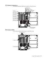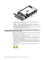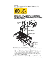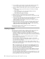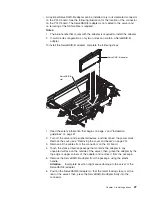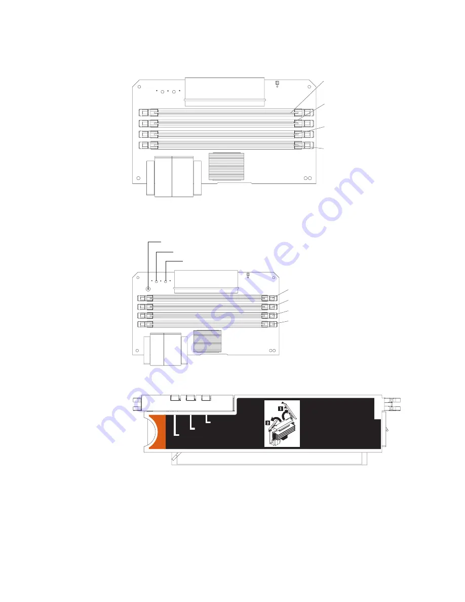
Memory-card
connectors
The
following
illustration
shows
the
connectors
on
the
memory
card.
DIMM 1
DIMM 2
DIMM 3
DIMM 4
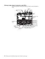
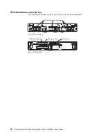
Memory-card
LEDs
The
following
illustration
shows
the
LEDs
on
the
memory
card.
DIMM 1 error LED
DIMM 2 error LED
DIMM 3 error LED
DIMM 4 error LED
Light path diagnostics button
Light path diagnostics button power LED
Memory card error LED
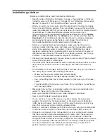
The
following
illustration
shows
the
top
view
of
the
memory
card.
Memory Hot-Swap Enabled
Memory Port Power
Error
Chapter
2.
Installing
options
17
Summary of Contents for 88743RU - System x3950 E
Page 1: ...IBM System x3950 Type 8878 and System x3950 E Type 8879 User s Guide...
Page 2: ......
Page 3: ...IBM System x3950 Type 8878 and System x3950 E Type 8879 User s Guide...
Page 68: ...56 IBM System x3950 Type 8878 and System x3950 E Type 8879 User s Guide...
Page 98: ...86 IBM System x3950 Type 8878 and System x3950 E Type 8879 User s Guide...
Page 100: ...88 IBM System x3950 Type 8878 and System x3950 E Type 8879 User s Guide...
Page 109: ......
Page 110: ...Part Number 31R1871 Printed in USA 1P P N 31R1871...

