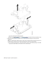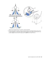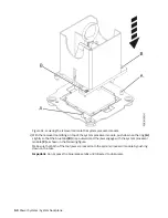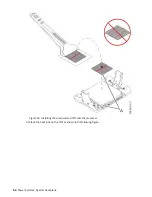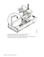
Figure 62. Replacing the I/O voltage regulator module
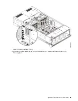
12. Replace the standby voltage regulator module in location P1-C22.
a) With the levers (A) in the open position, hold the voltage regulator module by its levers and lower
the voltage regulator module into its slot in the system. Refer to the following image.
b) Gently push the voltage regulator module into its connector.
c) Rotate the levers in the direction shown and press down on the latches to secure the voltage
regulator module in its slot.
System backplane for the 9040-MR9 61
Summary of Contents for 9040-MR9
Page 1: ...Power Systems System backplane for the 9040 MR9 IBM...
Page 4: ...iv...
Page 14: ...xiv Power Systems System backplane...
Page 17: ...or or or or System backplane for the 9040 MR9 3...
Page 98: ...84 Power Systems System backplane...
Page 109: ......
Page 110: ...IBM...


