Do not pull out or install any drawer or feature if the rack stabilizer brackets are not attached to the
rack. Do not pull out more than one drawer at a time. The rack might become unstable if you pull out
more than one drawer at a time.
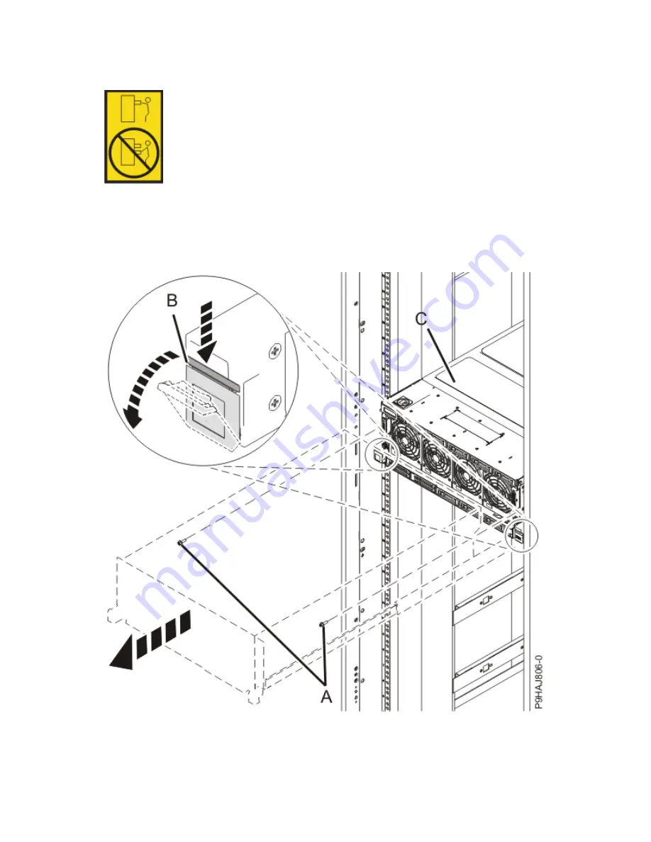
a. If not already removed, remove the shipping screws (A) as shown in the following figure by using a
Phillips screwdriver.
b. Release the side latches (B) by pressing them downward as shown in the following figure.
c. Pull out the system (C) as shown in the following figure. Ensure that any cables do not catch or bind
as you pull out the system.
Figure 33. Placing the system in service position
6. Attach the electrostatic discharge (ESD) wrist strap.
The ESD wrist strap must be connected to an unpainted metal surface until the service procedure is
completed, and if applicable, until the service access cover is replaced.
Memory riser for the 9040-MR9 47
Summary of Contents for 9040-MR9
Page 1: ...Power Systems Memory modules for the 9040 MR9 IBM ...
Page 4: ...iv ...
Page 14: ...xiv Power Systems Power Systems Memory ...
Page 17: ...Figure 1 Removing the power cords L003 or or Memory modules for the 9040 MR9 3 ...
Page 30: ...or or or or 16 Power Systems Power Systems Memory ...
Page 46: ...Figure 23 Removing the power cords L003 or or 32 Power Systems Power Systems Memory ...
Page 59: ...Figure 32 Removing the power cords L003 or or Memory riser for the 9040 MR9 45 ...
Page 70: ...Figure 40 Removing the power cords L003 or or 56 Power Systems Power Systems Memory ...
Page 86: ...or or or or 72 Power Systems Power Systems Memory ...
Page 105: ......
Page 106: ...IBM ...


