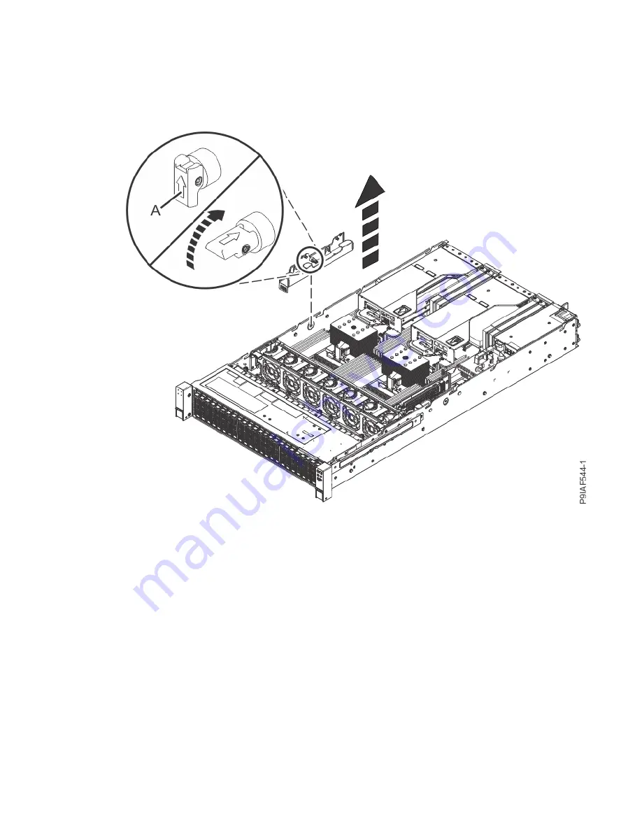
4. If the memory socket is covered by the drive cables and the drive cable holder on the left side of the
system, complete the following procedure.
a) Remove the drive cables from the drive cable holder.
Let the cables rest on the system processor heat sink.
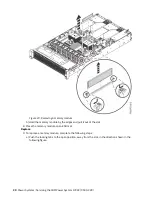
b) Retract the retaining pin (A) as shown in the following figure.
Figure 19. Retracting the retaining pin and removing the left cable holder
c) Lift the drive cable holder out of the system.
5. If the memory socket is covered by a PCIe riser at the rear of the system, move the PCIe riser out of
the way by using the following procedure.
a) Leave the cables plugged into the PCIe adapters.
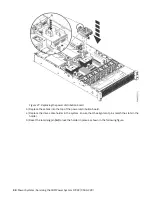
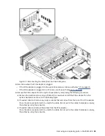
b) Lift the PCIe riser up, out of the system as shown in the following figure.
26 Power Systems: Servicing the IBM Power System IC922 (9183-22X)


