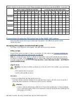
Table 2. Memory module population order. Memory module slot locations and number of DIMMs. (continued)
CPU 1 memory module slot locations
CPU 0 memory module slot locations
15
14
13
12
11
10
9
8
7
6
5
4
3
2
1
0
31
30
29
28
27
26
25
24
23
22
21
20
19
18
17
16
12 DIMMs
Y
Y
Y
Y
Y
Y
Y
Y
Y
Y
Y
Y
16 DIMMs
Y
Y
Y
Y
Y
Y
Y
Y
Y
Y
Y
Y
Y
Y
Y
Y
24 DIMMs
Y
Y
Y
Y
Y
Y
Y
Y
Y
Y
Y
Y
Y
Y
Y
Y
Y
Y
Y
Y
Y
Y
Y
Y
32 DIMMs
Y
Y
Y
Y
Y
Y
Y
Y
Y
Y
Y
Y
Y
Y
Y
Y
Y
Y
Y
Y
Y
Y
Y
Y
Y
Y
Y
Y
Y
Y
Y
Y
Removing and replacing PCIe adapters in the 9183-22X system
Find information about removing and replacing PCIe adapters in the IBM Power System IC922
(9183-22X) server.
Removing a PCIe adapter from the 9183-22X system
To remove a PCIe adapter from the system, complete the steps in this procedure.
Before you begin
Power off the system and place it in the service position. For instructions, see “Preparing the 9183-22X
system to remove and replace internal parts” on page 146.
Note: If a CacheVault power module is attached to the adapter, remove the CacheVault power module
and cable. For details, see the Broadcom web site (https://www.broadcom.com/products/storage/raid-
controllers/megaraid-sas-9361-8i). Select Documentation > Quick Installation Guides > LSICVM02 Kit
Quick Installation Guide.
About this task
Attention: For safety and airflow purposes, if you remove parts from the system, you must ensure
that:
• PCIe tailstock fillers are present.
• System airflow baffle is present.
Procedure
1. Attach the electrostatic discharge (ESD) wrist strap.
The ESD wrist strap must be connected to an unpainted metal surface until the service procedure is
completed, and if applicable, until the service access cover is replaced.
Attention:
• Attach an electrostatic discharge (ESD) wrist strap to the front ESD jack, to the rear ESD jack,
or to an unpainted metal surface of your hardware to prevent the electrostatic discharge from
damaging your hardware.
38 Power Systems: Servicing the IBM Power System IC922 (9183-22X)


