Installing and Removing Channel Adapters
This section explains how to perform channel adapter installation and replacement,
and shows how to connect and install the cables for the channel adapters.
Note: This procedure requires a channel-trained IBM service representative or
customers channel-trained person.
Parallel Channel Attachment
Up to six multiaccess enclosure base Parallel Channel Adapters can be attached to
a single channel. When the channel is configured for 4.5 MB Data Streaming, the
multiaccess enclosure base Parallel Channel Adapter must be a the end of the
channel.
The adapter attaches to the channel with the Channel Interface Cable group
(V-cable and two unique optional-order Channel Interface Cables). Figure 3-13 on
page 3-35 shows how the cables attach to the channel.
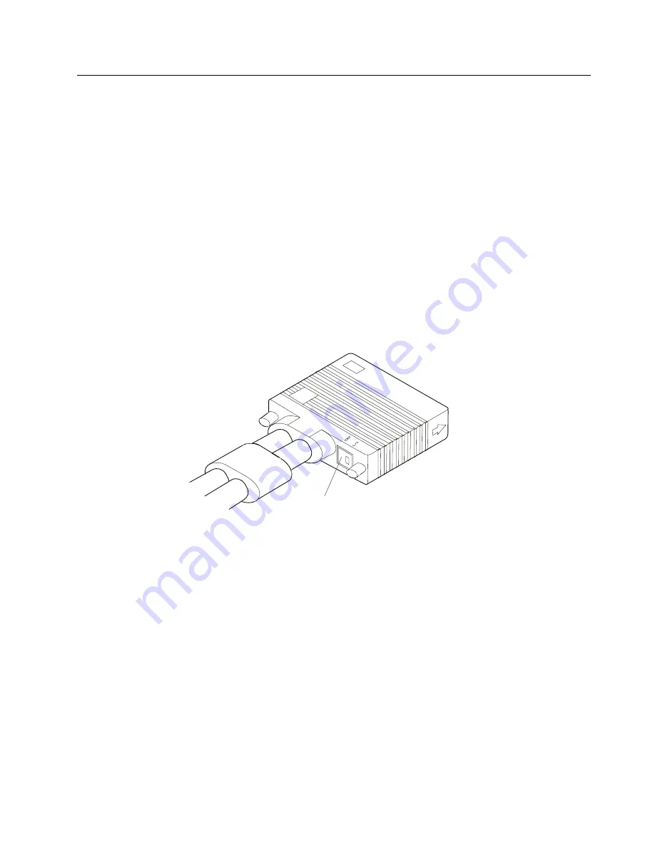
The V-cable, as shown in Figure 3-11, has a Select/Bypass Switch with settings of
S and B that are used to select or bypass this adapter, respectively.
Select/Bypass Switch
Figure
3-11. Select/Bypass Switch on V-Cable
Attention:
¹
During testing and installation, you may be instructed to use the Select/Bypass
Switch to bypass the adapter you are working on.
¹
Be sure to ask the host operator to vary the channel off before you use the
switch so that you will not disrupt the channel.
The cables are designed so that you can interconnect them in a serial fashion to
form a channel path. This enables you to connect several adapters without each
adapter connecting to a bus and tag channel cable.
The last Parallel Channel Adapter in the series must be terminated using either the
multiaccess enclosure base specific channel terminators (PN 25L4747), or Channel
Interface-out with standard bus and tag terminators. “Using Interconnected
V-Cables” on page 3-38 explains the concepts regarding Parallel Channel Adapter
interconnecting.
Chapter 3. Multiaccess Enclosure Problem Determination
3-33
Summary of Contents for 950
Page 2: ......
Page 12: ...x 3746 9X0 MAE Installation and Maintenance ...
Page 22: ...xx 3746 9X0 MAE Installation and Maintenance ...
Page 28: ...xxvi 3746 9X0 MAE Installation and Maintenance ...
Page 48: ...Go to Step 6 Customizing the MAE on page 1 21 1 20 3746 9X0 MAE Installation and Maintenance ...
Page 176: ...4 58 3746 9X0 MAE Installation and Maintenance ...
Page 184: ...Figure 5 4 Current Boot Sequence 5 8 3746 9X0 MAE Installation and Maintenance ...
Page 243: ...Installing Options Programming None Chapter 6 Installing Options 6 7 ...
Page 254: ...Installing Options 6 18 3746 9X0 MAE Installation and Maintenance ...
Page 258: ...Installing Options 7 4 3746 9X0 MAE Installation and Maintenance ...
Page 264: ...B 4 3746 9X0 MAE Installation and Maintenance ...
Page 266: ...C 2 3746 9X0 MAE Installation and Maintenance ...
Page 278: ...D 12 3746 9X0 MAE Installation and Maintenance ...
Page 294: ...E 16 3746 9X0 MAE Installation and Maintenance ...
Page 300: ...F 6 3746 9X0 MAE Installation and Maintenance ...
Page 302: ...G 2 3746 9X0 MAE Installation and Maintenance ...
Page 306: ...H 4 3746 9X0 MAE Installation and Maintenance ...
Page 382: ...X 6 3746 9X0 MAE Installation and Maintenance ...
Page 389: ......


