


(continued)
006 (continued)
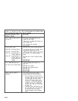
DOES THE HARDWARE CONFIGURATION REPORT CORRECTLY
IDENTIFY THE DEVICES INSTALLED IN THE SYSTEM UNIT?
Yes No
007
– The System Configuration Report shows only those devices
supported by the Diagnostics and Utilities CD and only
factory-installed devices for the model you are servicing.
– If a device is missing from the list and is not factory installed, refer
to the service manual provided for that device. (Refer to the
Appendix B, “Model/Monitor Configurations and FRU Part Numbers”
on page B-1 to determine the factory-installed devices in the model
you are servicing.)
– If a factory-installed drive device or adapter card is not listed in the
System Configuration Report, return to “Start” on page 2-2 and then
go to “Factory-Installed Drive Devices” on page 2-47.
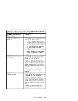
008
– Select Diagnostics Menu from the Main Menu.
– Select Easy Test Diagnostics from the Diagnostics Menu.
DOES THE EASY TEST FINISH WITHOUT ERROR CODES?
Yes No
009
– If the last test stops and you cannot continue, first make sure all
switches, power connectors, cables, and jumpers are set correctly
and show the correct voltages and continuity.
– Make note of any messages, error codes, beeps, or new symptoms.
Go to “Index of Symptoms, Messages, Error Codes, or Beeps” on
page 2-9.
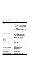
010
– The Easy Test Diagnostics did not detect a failure. If the system still
display a failure:
Check all adapter card jumper settings.
Check all adapter card switch settings.
Check all adapter card cables and connectors for proper installation.
Make sure all of the above are set correctly and show the correct
voltages and continuity. Replace any defective cables or adapter
cards. See “Power Supply” on page 2-34, “System Board
2-44
Summary of Contents for Aptiva 2140
Page 2: ......
Page 8: ...vi...
Page 24: ...xxii...
Page 26: ...xxiv...
Page 128: ...3 14...
Page 132: ...2010 Cover Do not lift the cover too high as the tabs might break 4 4...
Page 134: ...Figure 4 2 3 5 In Cage 4 6...
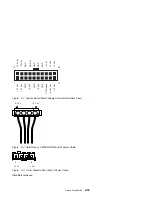
Page 136: ...JP7 JP6 JP4 J2 J1 Figure 4 4 Console cable removal 4 8...
Page 138: ...Figure 4 7 Removing the console 4 10...
Page 139: ...Figure 4 8 Removing the console bottom plate Figure 4 9 Console spring Repair Information 4 11...
Page 170: ...6 2...
Page 174: ...Assembly 2 Machine Type 2140 System Unit Interior SL A 1 3 4 5 6 2 7 4...
Page 178: ...Assembly 4 Machine Type 2142 System Unit Interior SL A 1 3 4 5 7 6 2 7 8...
Page 181: ...Assembly 5 Diskette Hard Disk Drives and Zip Drive 3 1 4 4 4 2 Parts Catalog 7 11...
Page 185: ...Assembly 7 CD DVD ROM Drive Modem and TV Cards 3 5 1 2 4 6 Parts Catalog 7 15...
Page 196: ...8 4...
Page 206: ...B 8...
Page 211: ......


